Sensitivity switchable detection circuit and method

a detection circuit and switchable technology, applied in the direction of electric variable regulation, process and machine control, instruments, etc., can solve the problems of reducing yield, uncomfortable feelings, and affecting the detection effect, so as to prevent the sudden change of the detected signal, reduce the effect of labor intensity and increase the manufacturing cos

Active Publication Date: 2008-06-03
DENSO CORP
View PDF17 Cites 3 Cited by
  • Summary
  • Abstract
  • Description
  • Claims
  • Application Information

AI Technical Summary

Benefits of technology

[0010]In view of the above-described problem, it is an object of the present invention to provide a sensitivity switchable detection circuit and method for reducing a sudden change in a detected signal, the sudden change occurring during a gain switching operation performed based on amplitude of an input signal.
[0011]A sensitivity switchable detection circuit includes a first detection circuit, a second detection circuit, and an output switching circuit. The first detection circuit has a first gain with respect to an input quantity and outputs a first signal proportional to the first gain. The second detection circuit has a second gain with respect to the input quantity and outputs a second signal proportional to the second gain. The output switching circuit switches between the first signal and the second signal based on their amplitudes and outputs a detected signal associated with the input quantity, thereby narrowing dynamic range of the detected signal. The first gain and the second gain are defined as the ratio of the amplitudes of the first signal and the second signal to the input quantity, respectively. The first gain is set higher than the second gain.
[0015]This approach prevents the sudden change in the detected signal during the gain region switching operation, even if the first detection circuit or the second detection circuit has gain errors. Further, the gradual gain region switching operation can be achieved by processing the first signal and the second signal by means of simple hardware or software. Therefore, the sensitivity switchable detection circuit can be manufactured without an increase in manufacturing cost and has much practical application.

Problems solved by technology

However, when the two gain regions are switched, a considerable change in a detected signal occurs between before and after the region switching operation, due to gain errors of amplifiers, circuit errors, or the like.
In the EPS control, the sudden change of the motor torque causes uncomfortable feelings in steering, for example.
However, such measures cause a reduction in yield and an increase in parts cost of the detection circuit, and therefore are not practical in most applications.

Method used


Image

  • Sensitivity switchable detection circuit and method
  • Sensitivity switchable detection circuit and method
  • Sensitivity switchable detection circuit and method

Examples


Embodiment Construction

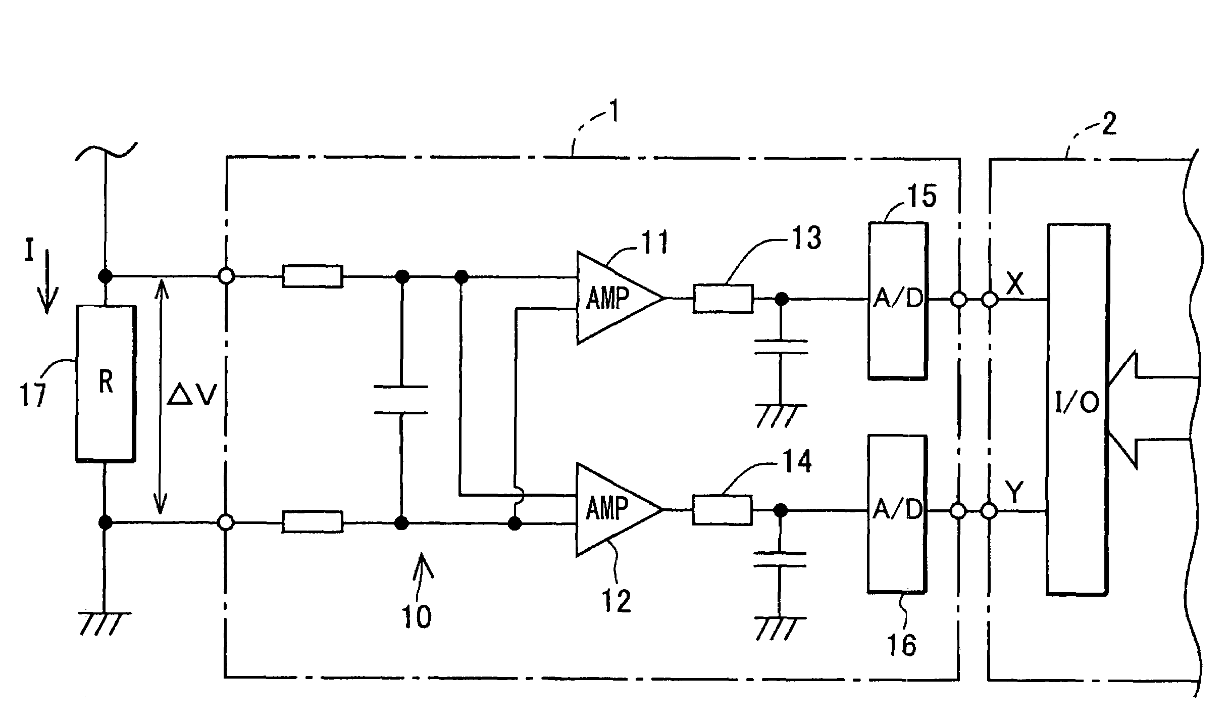
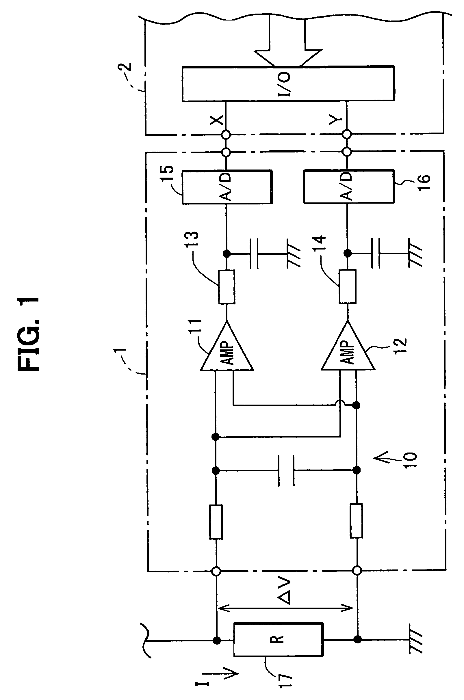
[0020]Reference is made to FIG. 1, which shows a circuit diagram of a sensitivity switchable detection circuit applied to a microcomputer 2 for controlling an actuator (not shown). A current detection circuit 1 is connected to a shunt resistor 17 having a resistance R to detect an input current I as an input quantity. The current detection circuit 1 converts a voltage ΔV appearing across the shunt resistor 17 to a digital signal and outputs the digital signal to an input / output (I / O) interface of the microcomputer 2. The microcomputer 2 functions as a control device for controlling steering assist torque. The microcomputer 2 controls an electric current of a motor as an actuator in such a manner the electric current changes in proportion to a steering force so that the motor produces a steering assist torque proportional to the steering force.

[0021]The current detection circuit 1 includes a RC low-pass filter 10 for extracting a low frequency component from the voltage ΔV, a first a...


PUM


Abstract

A sensitivity switchable detection circuit includes a high gain circuit for outputting a first signal, a low gain circuit for outputting a second signal, and an output switching circuit for switching between the first signal and the second signal. When the first signal is smaller than a lower limit, the first signal determines a detected signal. When the second signal is larger than an upper limit, the second signal determines the detected signal. When the first signal is larger than the lower limit and the second signal is lower than the upper limit, a weighting function that uses the first signal and the second signal as input variables determines the detected signal.

Description

CROSS REFERENCE TO RELATED APPLICATION[0001]This application is based on and incorporates herein by reference Japanese Patent Application No. 2005-82158 filed on Mar. 22, 2005.FIELD OF THE INVENTION[0002]The present invention relates to a sensitivity switchable detection circuit and method.BACKGROUND OF THE INVENTION[0003]Motor control apparatuses, for example, electric power steering (EPS) apparatus disclosed in U.S. Pat. No. 6,497,303 (JP-A-2002-12157) or JP-A-2003-2222 uses feedback control to make a motor current converge to a desired current value (i.e., torque command). In a small current range such that the desired value is small, the feedback control is generally required to produce the motor current precisely in accordance with a small change in the desired value. In contrast, in a large current range such that the desired value is large, the feedback control may not be required to produce the motor current precisely in accordance with the small change in the desired value,...

Claims


Application Information

Patent Timeline
Patent Type & Authority Patents(United States)
IPC IPC(8): G01R31/34B62D5/04G05F5/00H02P29/00
CPCB62D5/046
Inventor OHASHI, YUTAKAHAYASHI, JIROU
Owner DENSO CORP
Why Eureka
Try Eureka