Drive circuit for display apparatus and driving method

a technology of drive circuit and display apparatus, which is applied in the direction of instruments, static indicating devices, etc., can solve problems such as the degradation of image quality

Inactive Publication Date: 2006-11-23
RENESAS ELECTRONICS CORP
View PDF27 Cites 27 Cited by
  • Summary
  • Abstract
  • Description
  • Claims
  • Application Information

AI Technical Summary

Benefits of technology

[0092] Also, according to the present invention, it is possible to reduce noise caused by a transient current generated inside of the drive circuit and to improve image quality in the display apparatus.

Problems solved by technology

Also, noise is propagated to a Vcom voltage supplied to a common electrode in the display panel 3 from a power source circuit, resulting in degradation of a quality of an image caused by a horizontal stripe or a flicker.

Method used


Image

  • Drive circuit for display apparatus and driving method
  • Drive circuit for display apparatus and driving method
  • Drive circuit for display apparatus and driving method

Examples


first embodiment

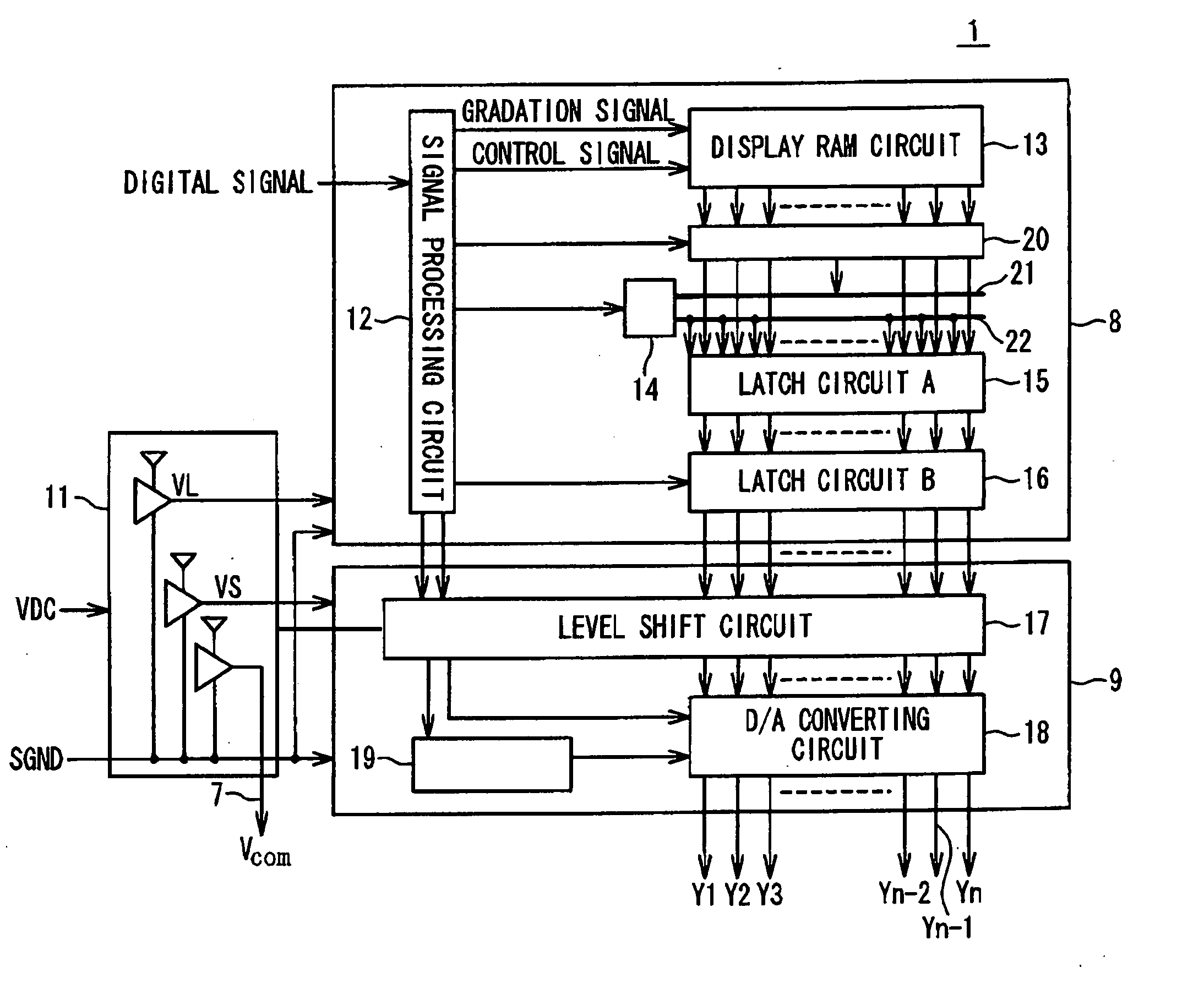
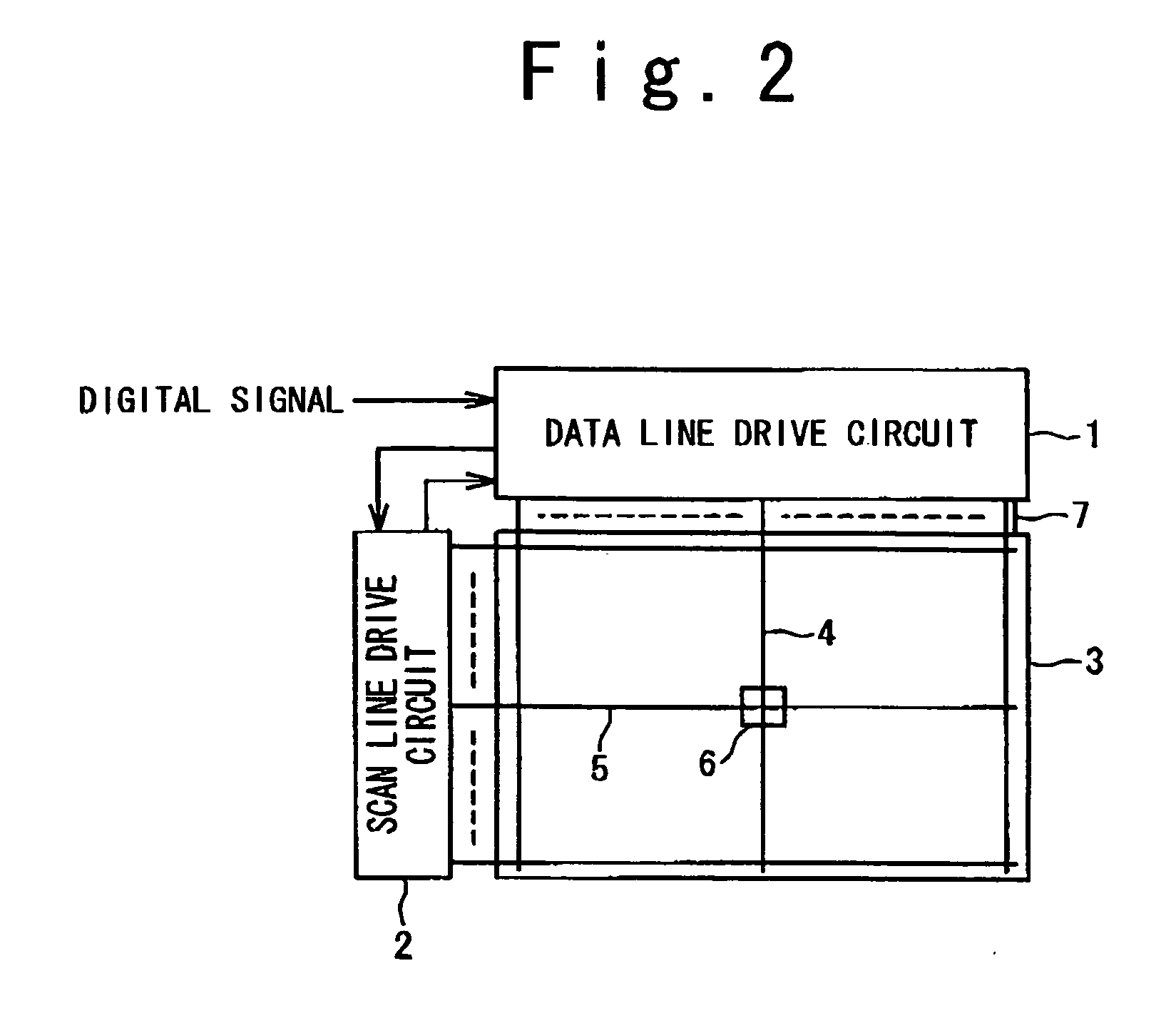
[0047]FIG. 2 is a block diagram showing the drive circuit according to the first embodiment of the present invention. Referring to FIG. 2, the drive circuit according to the first embodiment of the present invention can be applied to a display apparatus of a mobile phone. The display apparatus is provided with a data line drive circuit 1, a scanning line drive circuit 2 and a display panel 3. The data line drive circuit 1 incorporates a display memory (RAM) circuit 13. The display apparatus receives a digital signal from a CPU (not shown) in the mobile phone or the like. Examples of such a digital signal include a digital gradation data signal of 6 bits representing a contrast of a color of each of pixels and control signals such as an address control signal for designating a region of the display memory circuit 13 for the gradation data to be written in, a command signal and a standby signal.

[0048] The display memory circuit 13 stores the gradation data for one frame. In the drive...

second embodiment

[0080] Next, the drive circuit according to the second embodiment of the present invention will be described. The description of the same components as those of the first embodiment will be omitted below, and only different points will be described.

[0081]FIG. 11 is a block diagram illustrating the configuration of the drive circuit for the display apparatus in the second embodiment. Although the two groups of the data buses 21 and 22 are provided in the first embodiment, a single data bus 23 is provided and is shared in the second embodiment. Xn other words, gradation data is supplied from the display memory circuit 13 to the data calculating circuit 14 through the buffer circuit 20 and the data bus 23, and display pixel data, which has been subjected to a predetermined signal process in the data calculating circuit 14, is also supplied to the data latch circuit A 15 through the data bus 23. The buffer circuit 20 and the data calculating circuit 14 alternately use the data bus 23 i...

third embodiment

[0083] Next, the drive circuit according to the third embodiment of the present invention will be described below in detail. The description of the same components as those of the first embodiment will be omitted below, and only different points will be explained. FIG. 13 is a block diagram illustrating the configuration of the drive circuit for the display apparatus in the third embodiment. Differences from the first embodiment are present in that the logic unit 8 includes a data calculating circuit 24 in place of the data calculating circuit 14 and additionally includes a determination signal bus 25. Furthermore, the drive unit 9 includes a gradation voltage generating circuit 26 in place of the gradation voltage generating circuit 19 and a D / A converting circuit 28 in place of the D / A converting circuit 18.

[0084] As shown in FIG. 14, the data calculating circuit 24 is configured such that a data determining circuit 50 is interposed between the logic circuit 37 and the majority l...


PUM


Abstract

A drive circuit includes a logic section having a data bus and a display memory circuit and configured to read out a plurality of gradation data from the display memory circuit through the data bus and to collectively output the plurality of gradation data as display pixel data; and a drive section configured to drive a display unit based on analog gradation signals which are generated based on the display pixel data outputted from the logic section. The drive circuit further includes a power supply circuit configured to supply at least one of first and second power supply voltages to the logic section and the drive section. The logic section, the drive section and the power supply circuit may be formed in a same semiconductor chip.

Description

BACKGROUND OF THE INVENTION [0001] 1. Field of the Invention [0002] The present invention relates to a drive circuit for a display apparatus, and more particularly to a drive circuit having a display memory for a display apparatus and a semiconductor device having the drive circuit integrated therein. [0003] 2. Description of the Related Art [0004] A liquid crystal display apparatus has prevailed as a type of display apparatus. Such a liquid crystal display apparatus has been adopted in various kinds of electronic equipment such as a mobile phone from its features of low power consumption, a light weight and thinness. A drive system for the liquid crystal display apparatus is classified into a simple matrix type and an active matrix type using an active device such as a thin film transistor (TFT) for a pixel circuit. The display apparatus displays a variety of video images in response to a digital signal supplied from a CPU in a mobile phone or the like. The digital signal includes ...

Claims


Application Information

Patent Timeline
Patent Type & Authority Applications(United States)
IPC IPC(8): G09G3/36
CPCG09G3/3685G09G2360/16G09G2310/027G09G3/3696
Inventor HASHIMOTO, YOSHIHARUTAHATA, TAKASHIKUMETA, MASAYUKIYAMAGAMI, YUTAKAKATO, HISANAO
Owner RENESAS ELECTRONICS CORP
Why Eureka
Try Eureka