Diffusion lens for diffusing LED light

a technology of led light and diffusion lens, which is applied in the field of diffusion lens for diffusing light, can solve the problems of difficult ejection of plastic lens from mold, difficult to produce mold, and practicable production of diffusion lens, and achieve the effect of facilitating the ejection of diffusion lens

Active Publication Date: 2006-11-23
SEKONIX
View PDF2 Cites 29 Cited by
  • Summary
  • Abstract
  • Description
  • Claims
  • Application Information

AI Technical Summary

Benefits of technology

[0014] Accordingly, the present invention has been made keeping in mind the above problems occurring in the prior art, and an object of the present invention is to provide the shape of a diffusion lens for diffusing LED light, which facilitates the ejection of the diffusion lens after the production of a mold and molding have been performed when the diffusion lens for diffusing LED light is produced, and which uniformly diffuses LED light in the central direction, the diagonal direction and the lateral direction of the lens.

Problems solved by technology

Since the conventional diffusion lens has a very complicated shape, it is not practical to produce the diffusion lens by polishing and processing glass, so the diffusion lens is generally produced through injection using a plastic material as the material.
However, there is a disadvantage in that, even if a plastic injection process is employed, it is difficult to eject a plastic lens from a mold after the molding of the plastic lens has been completed, because of the funnel-shaped protrusion and the depressed part on the side surface, and it is also not easy to produce the mold of the lens.
Further, since LED light incident on the first lens surface 20 is refracted to the top of the lens in a range adjacent to the central axis of the lens, or is totally reflected when the LED light is incident on a side surface compared to the central axis, it is difficult to adjust the amount of light of illumination passing through the center portion of the lens, using upper refracted light, refracted from the first lens surface.
That is, most LED light incident on the first lens surface is totally reflected, and refraction is very limitedly conducted only around the central axis of the lens, so that a phenomenon in which the center portion of the lens is darker than the surrounding portion of the lens may easily occur.

Method used


Image

  • Diffusion lens for diffusing LED light
  • Diffusion lens for diffusing LED light
  • Diffusion lens for diffusing LED light

Examples


Embodiment Construction

[0027] Hereinafter, embodiments of the present invention will be described in detail with reference to the attached drawings.

[0028] Reference now should be made to the drawings, in which the same reference numerals are used throughout the different drawings to designate the same or similar components.

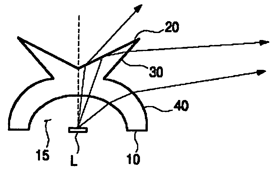
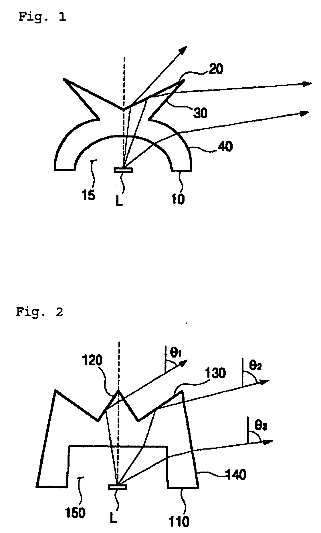
[0029]FIG. 2 illustrates the shape of a diffusion lens for diffusing Light Emitting Diode (LED) light and the diffusion trace thereof according to an embodiment of the present invention. As shown in FIG. 2, the diffusion lens for diffusing LED light can be packaged as a single luminous element assembly, together with an LED chip using a well-known method.

[0030] As shown in the drawing, the diffusion lens for diffusing LED light according to an embodiment of the present invention includes a bottom surface 110 on which LED light is incident, a conic first lens surface 120 upwardly protruded along the central axis of the lens, a second lens surface 130 upwardly inclined from the outer e...


PUM


Abstract

Disclosed herein is a diffusion lens for diffusing LED light. The diffusion lens of the present invention includes a bottom surface, a conic first lens surface, a second lens surface, and a third lens surfaces. According to the present invention, it is easy to manufacture a mold required to manufacture a diffusion lens for diffusing LED light, and to eject the diffusion lens after molding has been performed, and it can uniformly diffuse LED light in the central direction, the diagonal direction and the lateral direction of the lens.

Description

RELATED APPLICATIONS [0001] The present disclosure relates to subject matter contained in priority Korean Application No. 10-2005-0042985 filed on 23 May 2005, which is herein expressly incorporated by reference in its entirety. BACKGROUND OF THE INVENTION [0002] 1. Field of the Invention [0003] The present invention relates, in general, to a diffusion lens for diffusing light emitted from a light emitting diode and, more particularly, to a diffusion lens for diffusing light emitted from a light emitting diode, which uniformly diffuses light that is emitted from a light emitting diode, employed as a light source for backlighting a liquid crystal display, in the central direction, the diagonal direction and lateral direction of the lens. [0004] 2. Description of the Related Art [0005] A display device, lacking a function of emitting light by itself, such as a Liquid Crystal Display (LCD), must use a separate light source for backlighting. For this function, a fluorescent lamp, such a...

Claims


Application Information

Patent Timeline
Patent Type & Authority Applications(United States)
IPC IPC(8): G02B13/20F21V5/00F21V5/04F21Y101/02G02B3/04G02B13/00G02B13/18G02B17/08H01L33/00H01L33/58
CPCH01L33/58H01L33/60G02B19/0061G02B19/0028G02B19/0071
Inventor CHOI, SOON CHEOL
Owner SEKONIX
Why Eureka
Try Eureka