Multifunctional-type backlight unit and information device using said backlight unit

Active Publication Date: 2006-11-23
CITIZEN ELECTRONICS CO LTD
View PDF2 Cites 72 Cited by
  • Summary
  • Abstract
  • Description
  • Claims
  • Application Information

AI Technical Summary

Benefits of technology

[0031] Thereby, it is possible to achieve optical communication or receiving of solar light efficiently by uti

Problems solved by technology

The disclosed infrared communication device is limited to low power transmission, in view of the need to protect the eyes of a user or persons in the vicinity.
As a result, the infrared communication device has problems of limited communication distance, resulting in communication failure of long distance.
Also, there is a problem of low communication speed.
However, it is difficult to achieve a wide generalization of the technology, because there are strict limitations on the output and also frequencies of the electric wave may influence on the human bod

Method used


Image

  • Multifunctional-type backlight unit and information device using said backlight unit
  • Multifunctional-type backlight unit and information device using said backlight unit
  • Multifunctional-type backlight unit and information device using said backlight unit

Examples


first embodiment

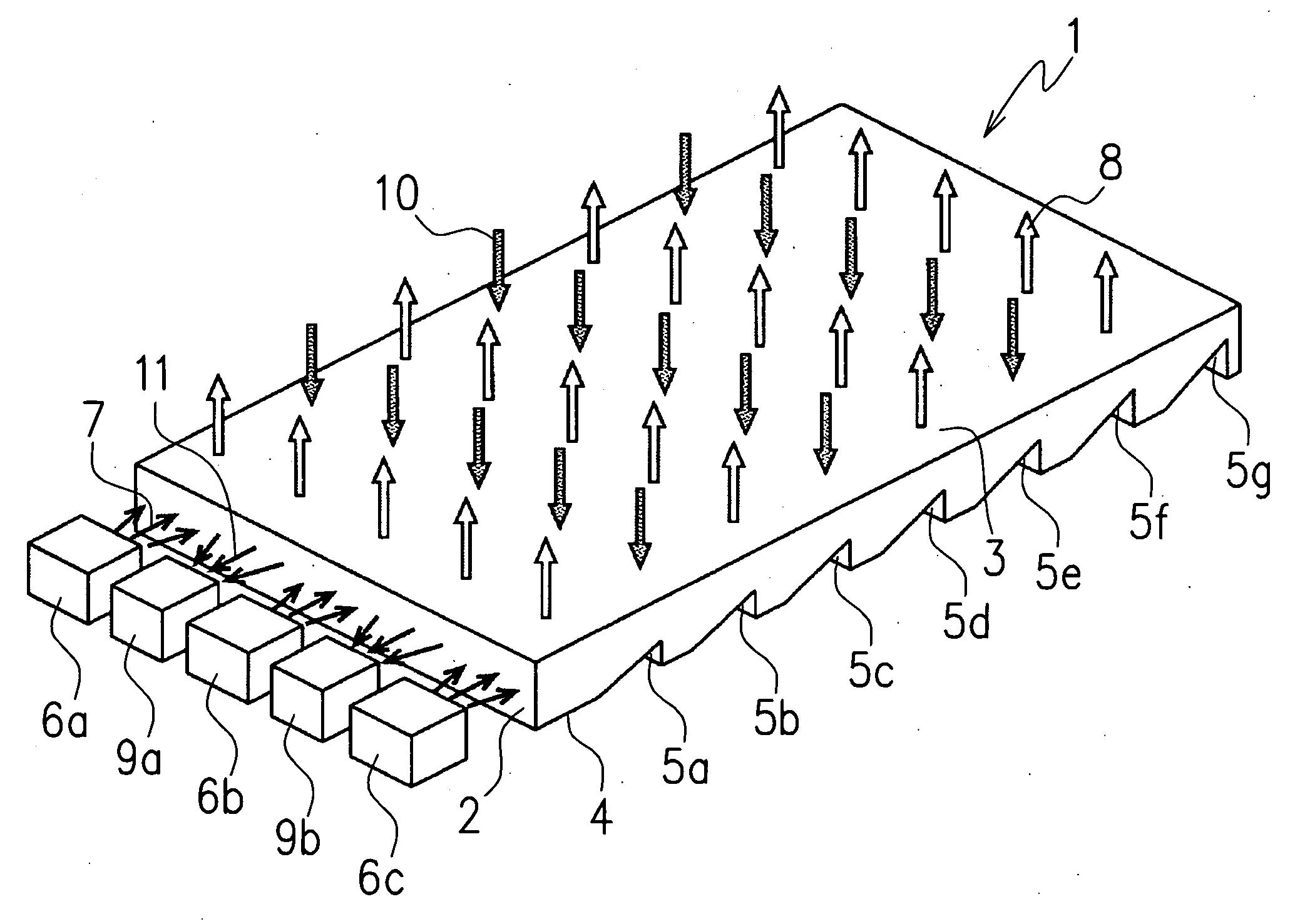
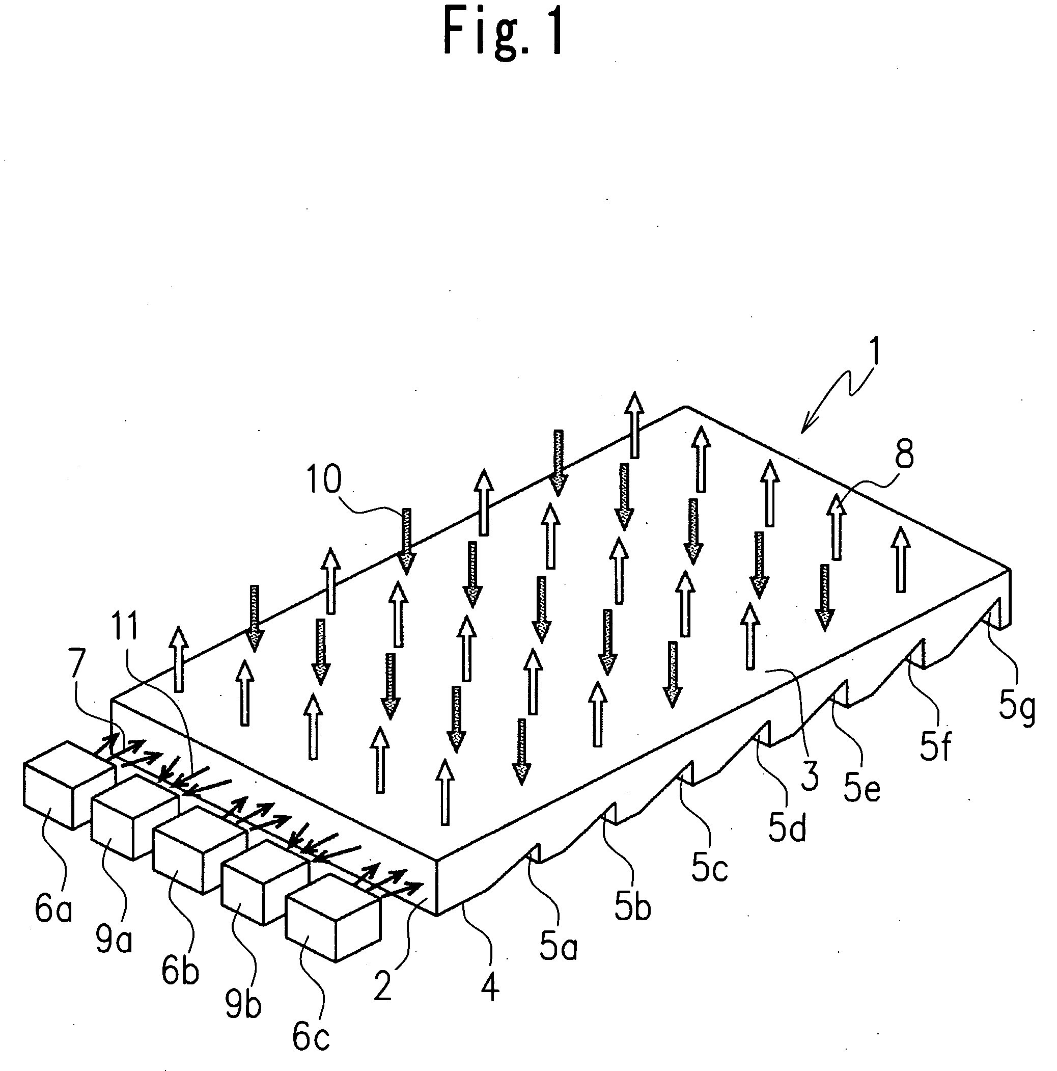
[0043]FIG. 1 illustrates a multifunctional-type backlight unit according to the present invention.

[0044] The multifunctional-type backlight unit includes a light guiding plate 1, a light emitting device to send light to the light guiding plate 1 and a light receiving device to receive light from the light guiding plate 1. The light guiding plate 1 has a generally rectangular shape with a predetermined thickness and can be made of any transparent material.

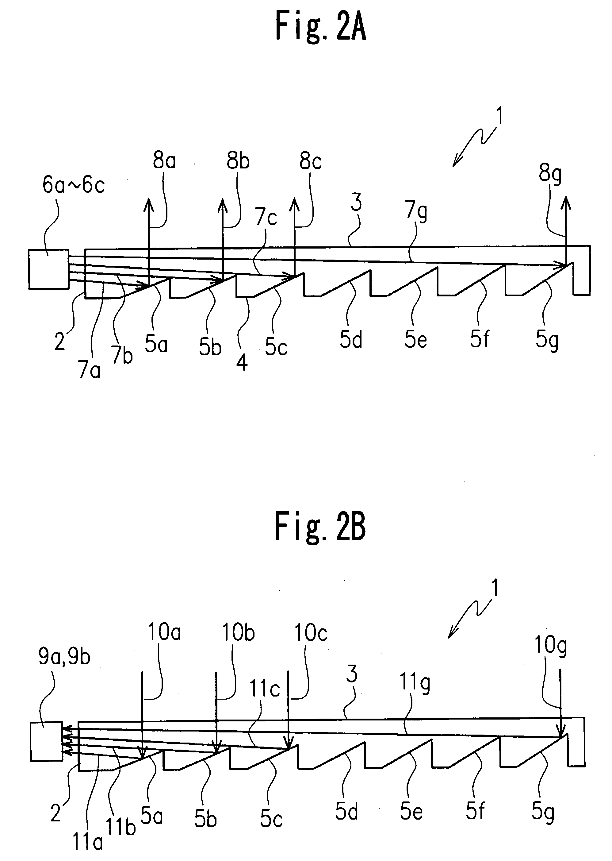
[0045] The light guiding plate 1 includes, for example, a first incident / exit surface 2 which is provided on one side surface of the light guiding plate 1 and is capable of inputting incident light 7 and outputting outgoing light 11, a second incident / exit surface 3 which is provided on an upper surface of the light guiding plate and is capable of inputting incident light 10 and outputting outgoing light 8, and a transmission mechanism provided on a lower surface 4 of the light guiding plate 1 and configured to transmit light from ...

second embodiment

[0111] Next, the multifunctional-type backlight unit according to the present invention is described referring to FIG. 3.

[0112] In this embodiment, modulated light function is added to the multifunctional-type backlight unit.

[0113] Because a structure of the second embodiment is the same as that of the first embodiment, a description of the structure is omitted, while the operation is described referring to FIG. 3.

[0114] In FIG. 3, the control apparatus 21 outputs the backlight control signal P1 comprising a digital signal of three bits. The backlight drive circuit 22 inputs the backlight control signal P1, executes a D / A conversion therein, and outputs the backlight drive signal P2 which is analogue voltage.

[0115] Moreover, the control apparatus 21 outputs the switching signal P5 which is a one-bit digital signal of logical “0” to control the switching circuit 24. When the switching signal P5 of logical “0” is input to the switching circuit 24, the switching circuit 24 selects t...


PUM


Abstract

A multifunctional-type backlight unit, including a light guiding plate having a first incident/exit surface and a second incident/exit surface which are capable of receiving and emitting light, a light emitting device disposed to face the first incident/exit surface and configured to supply light to the first incident/exit surface, and a light receiving device disposed to face the first incident/exit surface and configured to receive light emitted from the first incident/exit surface, the light guiding plate being configured so that the light emitted from the light emitting device enters the light guiding plate, passes through the light guiding plate, and is emitted from the second incident/exit surface, and the light guiding plate being configured so that the light which enters the second incident/exit surface, passes through the light guiding plate emits from the first incident/exit surface is received by the light receiving device.

Description

CROSS-REFERENCE TO THE RELATED APPLICATION [0001] This application is based on and claims priority from Japanese Patent Application No. 2005-137179, filed on May 10, 2005, the disclosure of which is incorporated herein by reference in its entirety. BACKGROUND OF THE INVENTION [0002] 1. Field of the Invention [0003] The present invention relates to a multifunctional-type backlight unit which is configured to give an optical communication function and a solar light collection function to a backlight unit for illumination of a display, and an information device using the multifunction-type backlight unit. [0004] 2. Description of Related Art [0005] In general, a liquid crystal panel combined with a backlight unit utilizing surface emission from a light guiding plate comprised in the backlight unit has been used as a display for a mobile phone, a personal computer, or the like. Various improvements in the backlight unit have been made. [0006] An improved light guiding plate to accomplis...

Claims


Application Information

Patent Timeline
IPC IPC(8): F21V7/04H04B10/116H04B10/524H04B10/11H04B10/54H04B10/80H04M1/00H04M1/02
CPCG02B6/0068G02B6/0038G02F1/1335
Inventor FUKASAWA, KOICHIISHIZAKA, MITSUNORI
Owner CITIZEN ELECTRONICS CO LTD
Why Eureka
Try Eureka