Airborne acoustic sensor array

Inactive Publication Date: 2006-11-23
HONEYWELL INT INC
View PDF8 Cites 14 Cited by
  • Summary
  • Abstract
  • Description
  • Claims
  • Application Information

AI Technical Summary

Benefits of technology

[0008] By allowing for remote deployment of the sensor array, the apparatus eliminates the need for soldiers to deploy arrays manually. In addition, the apparatus may comprise larger arrays, capable of greater acc

Problems solved by technology

However, they measure the bearing angle with an error having a standard deviation greater than four degrees.
Larger arrays, however, typically cannot be deployed from aircraft or by artillery.
Therefore, they must be installed manually by soldiers, which jeopardizes the soldiers' safety.
While s

Method used


Image

  • Airborne acoustic sensor array
  • Airborne acoustic sensor array
  • Airborne acoustic sensor array

Examples


Embodiment Construction

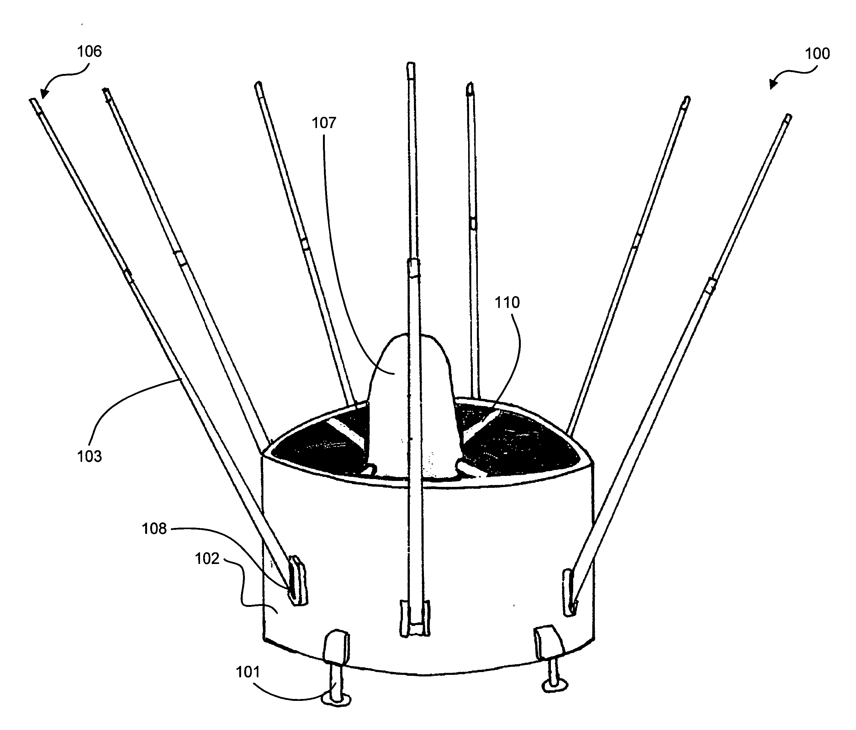
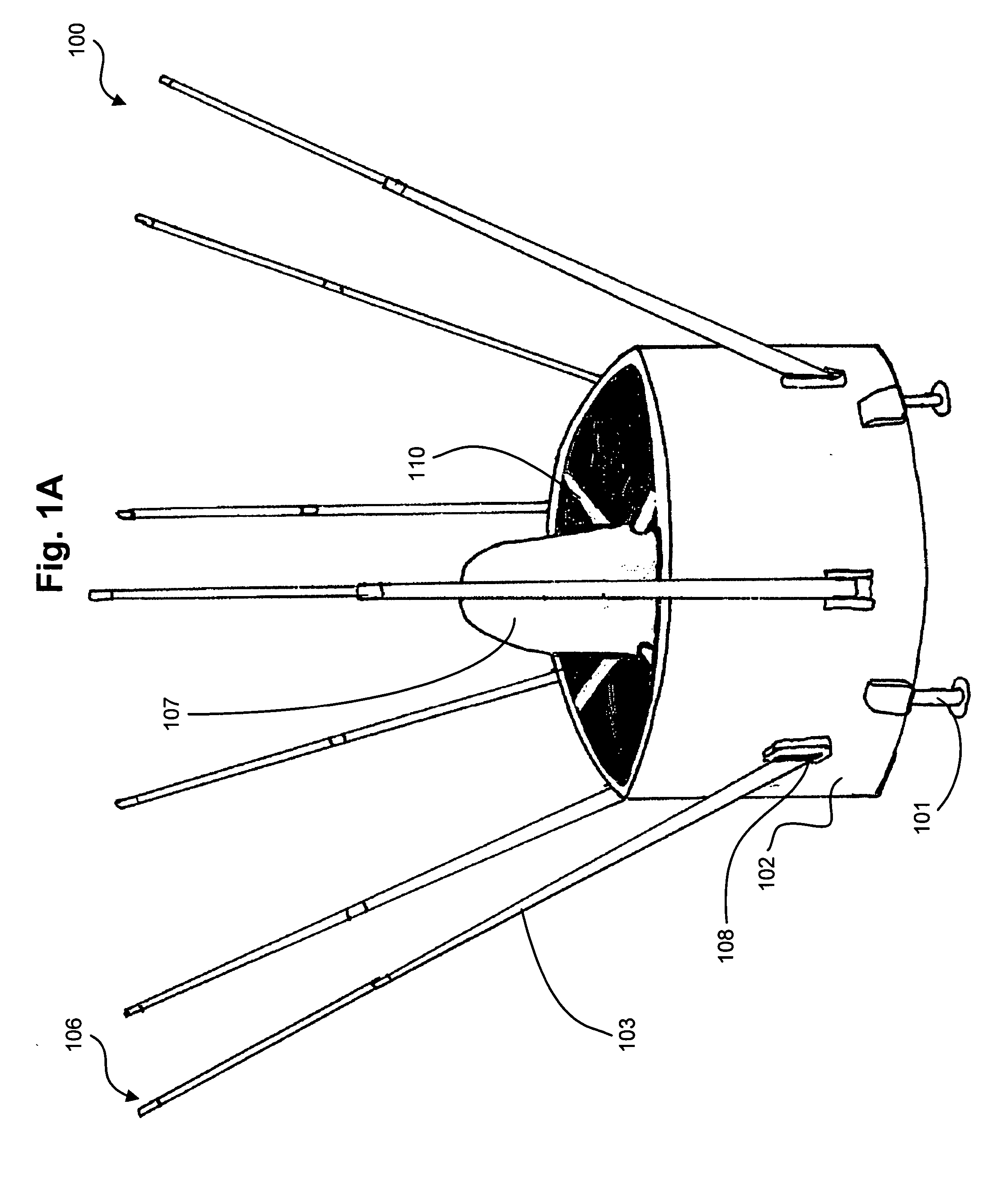
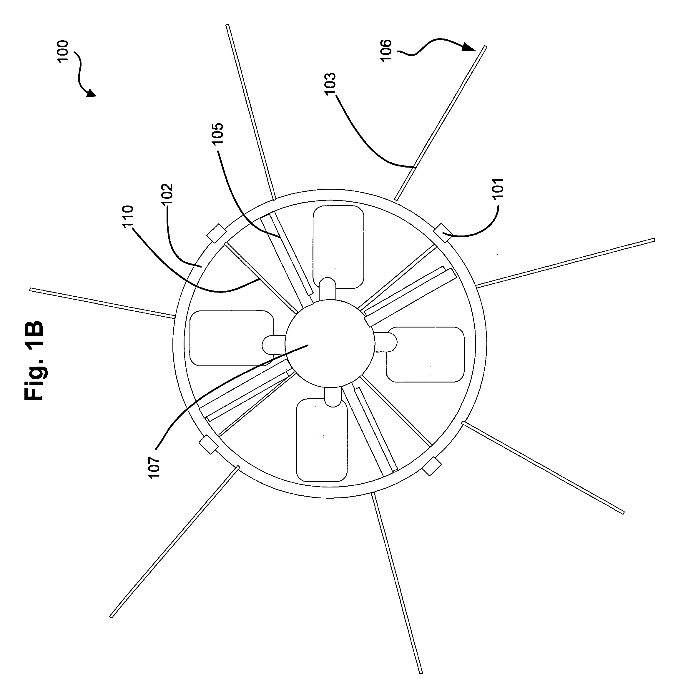
[0014]FIGS. 1A and 1B are perspective and plan views showing an apparatus 100 for determining the bearings to one or more targets, according to one embodiment of the present invention. The apparatus is operable to fly to a predetermined location and detect acoustic sound waves emitted by the target. The acoustic sensors 106 may detect the acoustic sound waves both during flight and after landing at the predetermined location. With the detected acoustic sound waves, a signal processing system, such as that described with reference to FIG. 4, can determine the bearing to the target and transmit the bearing to a remote location, such as a military base camp or artillery station.

[0015] The apparatus 100 has a propulsion system to enable flight. The propulsion system may consist of a duct 102, an impeller 104 (FIG. 1B), vanes 105, and an engine. In a preferred embodiment the engine is contained within the central housing unit 107. To provide flight, the impeller 104 rotates, forcing air...


PUM


Abstract

Embodiments for determining the bearings to targets from a remote location are disclosed. The apparatus consists of an array of acoustic sensors that is capable of autonomous flight. The array may be large in diameter, approximately one meter or greater. The apparatus is capable of navigating its flight to arrive at a predetermined location, measuring acoustic sound waves emitted by targets both during flight and after landing. The apparatus may then calculate the bearings to the targets and transmit this information to a remote location.

Description

BACKGROUND [0001] Acoustic sensor arrays protect soldiers by allowing for long range detection, tracking, and classification of enemy vehicles. An acoustic sensor array may consist of several sensors arranged in a circle which pick up acoustic data and use it to calculate the bearing angles to one or more targets. If two or more arrays are available, geometric triangulation may be used to pinpoint the location of the targets, and transmit this to a remote location via a transmitter. Currently, larger arrays must be manually installed by soldiers, while smaller arrays may be deployed by aircraft or artillery. [0002] Smaller arrays, such as those where the sensors are arranged on a circle with a diameter of approximately fifteen centimeters or less, do not require installation by soldiers. However, they measure the bearing angle with an error having a standard deviation greater than four degrees. The magnitude of this error means the arrays must be placed close to the target to be acc...

Claims


Application Information

Patent Timeline
IPC IPC(8): G01S3/80
CPCB64C39/024B64C2201/027B64C2201/042B64C2201/108G01S3/8083B64C2201/141B64C2201/162B64C2201/165F42B12/365B64C2201/127B64U10/13B64U50/19B64U30/20B64U2101/30B64U2201/10B64U50/14B64U50/13
Inventor HORAK, DAN T.BURNE, RICHARD A.
Owner HONEYWELL INT INC
Why Eureka
Try Eureka