Phase locking in a multi-channel quantum communication system

Inactive Publication Date: 2006-11-23
ALCATEL-LUCENT USA INC +2
View PDF11 Cites 13 Cited by
  • Summary
  • Abstract
  • Description
  • Claims
  • Application Information

AI Technical Summary

Benefits of technology

[0010] Problems in the prior art are addressed, in accordance with the principles of the present invention, by a communication system having a transmitter coupled to a receiver via a transmission link and adapted to use wavelength (frequency) division multiplexing for quantum-key distribution (QKD). In one embodiment, the receiver comprises an optical modulator (OM), a homodyne detector, and a signal processor. The OM is adapted to phase-shift a local oscillator (LO) signal generated at the receiver. The homodyne detector is adapted to (i) combine the LO signal with a quantum-information (QI) signal received via the transmission link from the transmitter to produce two interference signals and (ii) measure the intensity difference between these interference signals. The processor is adapted to process the measurement result to generate a control signal, which causes the phase shift(s) produced in the OM to establish a phase lock between the LO and QI signals. In one configuration, the QI signal has

Problems solved by technology

No method substantially more efficient than trying all 256 possible values of the key is known for breaking the DES.
Although a communication system employing one-time pads is theoretically secure against attacks based on sheer computational power, nevertheless, such a system has to deal with what is known as the key-distribution problem, i.e., the problem of securely furnishing keys to the transmitting/receiving stations.
With conventional (classical) key transmission methods, which can be subject to passive

Method used


Image

  • Phase locking in a multi-channel quantum communication system
  • Phase locking in a multi-channel quantum communication system
  • Phase locking in a multi-channel quantum communication system

Examples


Embodiment Construction

[0021] Reference herein to “one embodiment” or “an embodiment” means that a particular feature, structure, or characteristic described in connection with the embodiment can be included in at least one embodiment of the invention. The appearances of the phrase “in one embodiment” in various places in the specification are not necessarily all referring to the same embodiment, nor are separate or alternative embodiments mutually exclusive of other embodiments.

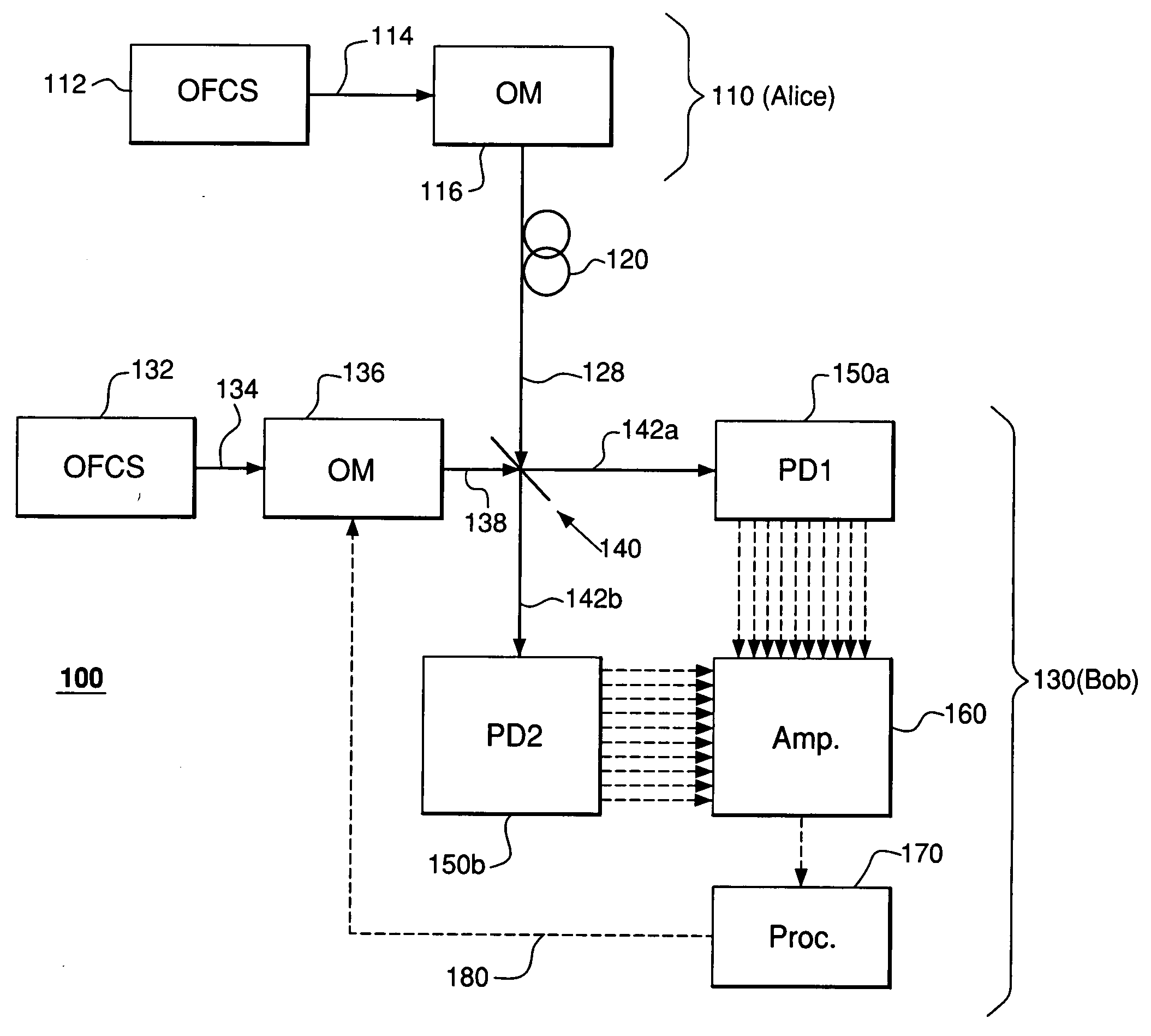
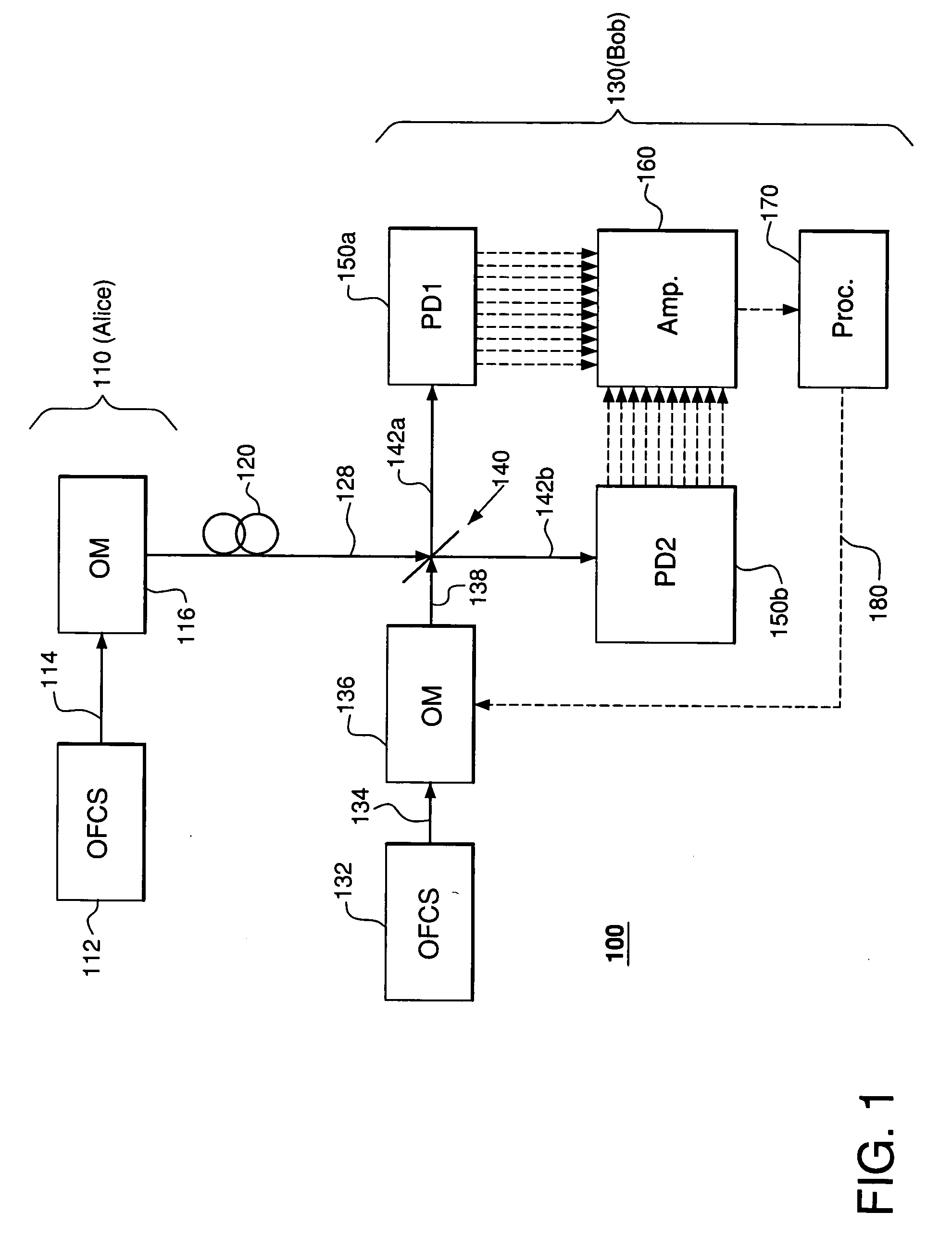
[0022]FIG. 1 schematically shows a multi-channel quantum communication system 100 according to one embodiment of the invention. More specifically, system 100 is adapted to use wavelength (frequency) division multiplexing for quantum-key distribution (QKD). System 100 has a transmitter 110 (Alice) and a receiver 130 (Bob) coupled via a transmission link (e.g., an optical fiber) 120. Transmitter 110 has an optical-frequency comb source (OFCS) 112 coupled to an optical modulator (OM) 116. OFCS 112 generates an optical signal 114 hav...


PUM


Abstract

A communication system adapted to use wavelength (frequency) division multiplexing for quantum-key distribution (QKD) and having a transmitter coupled to a receiver via a transmission link. In one embodiment, the receiver is adapted to (i) phase-shift a local oscillator (LO) signal generated at the receiver, (ii) combine the LO signal with a quantum-information (QI) signal received via the transmission link from the transmitter to produce interference signals, (iii) measure an intensity difference for these interference signals, and (iv) phase-lock the LO signal to the QI signal based on the measurement result. In one configuration, the QI signal has a plurality of pilot frequency components, each carrying a training signal, and a plurality of QKD frequency components, each carrying quantum key data. Advantageously, the system can maintain a phase lock for the QKD frequency components of the QI and LO signals, while the QKD frequency components of the QI signal continuously carry quantum key data.

Description

CROSS-REFERENCE TO RELATED APPLICATIONS [0001] This application claims priority from U.S. Provisional Patent Application No. 60 / 681,726 filed May 17, 2005, and entitled “Quantum Key Distribution.” The subject matter of this application is related to that of U.S. patent application Ser. No. ______, filed on the same date as the present application, and entitled “Multi-Channel Transmission of Quantum Information,” which is incorporated herein by reference in its entirety.BACKGROUND OF THE INVENTION [0002] 1. Field of the Invention [0003] The present invention relates to optical communication equipment and, more specifically, to equipment for transmission of encrypted data using quantum cryptography. [0004] 2. Description of the Related Art [0005] Cryptography is often used to exchange messages between two or more nodes (users, stations) in enhanced or even perfect privacy. A typical cryptographic method employs a publicly announced encrypting / decrypting algorithm, with the confidentia...

Claims


Application Information

Patent Timeline
IPC IPC(8): H04K1/00
CPCH04L9/0858
Inventor DINU, MIHAELADORRER, CHRISTOPHE J.GILES, CLINTON RANDYKANG, INUKMAROM, DAN MARK
Owner ALCATEL-LUCENT USA INC
Why Eureka
Try Eureka