Bone vibrating speaker using the diaphragm and mobile phone thereby

a technology of diaphragm and mobile phone, which is applied in the direction of transducer details, electrical transducers, telephone set constructions, etc., can solve the problems of too many problems for commercial implementation of the utility model, too low output sound pressure, and too many problems for the utility model to be implemented

Inactive Publication Date: 2006-11-23
LEE OUG KI +1
View PDF2 Cites 71 Cited by
  • Summary
  • Abstract
  • Description
  • Claims
  • Application Information

AI Technical Summary

Benefits of technology

[0028] According to the present invention, the bone conduction speaker has a function of vibrational hearing together with a function of an acoustic hearing, so that it is possible to obtain an effect that the user can select one of the function...

Problems solved by technology

However, some of the human beings having auditory disorders such as disorders of external ears or middle ears, presbycusis which is a hearing loss that gradually occurs, as they grow older, and hearing loss as an occupational disease cannot hear the sound in the only specific frequency range or all over the frequency range.
However, bone conduction telephone and the hearing aid vibrator by using the piezoelectric device according to the utility model are too theoretical to be implemented.
The utility model has so many problems for its commercial implementation.
Since the piezoelectric device has high impedance and high input voltage, the output sound pressure is too low and the miniaturization of the products is too difficult.
However, the conventional bone conduction speaker has a problem that high driving voltage and high power consumption are necessary to vibrate the yoke, the magnet, and the upper plate since the yoke, the magnet, and the upper plate serve as parts for generating the magnetic field as well as parts of vibrating upwardly and downwardly.
Therefore, the conventional bone conduction speaker has another problem that it is difficult to be miniaturized and employed to a subminiature mobil...

Method used


Image

  • Bone vibrating speaker using the diaphragm and mobile phone thereby
  • Bone vibrating speaker using the diaphragm and mobile phone thereby
  • Bone vibrating speaker using the diaphragm and mobile phone thereby

Examples


first embodiment

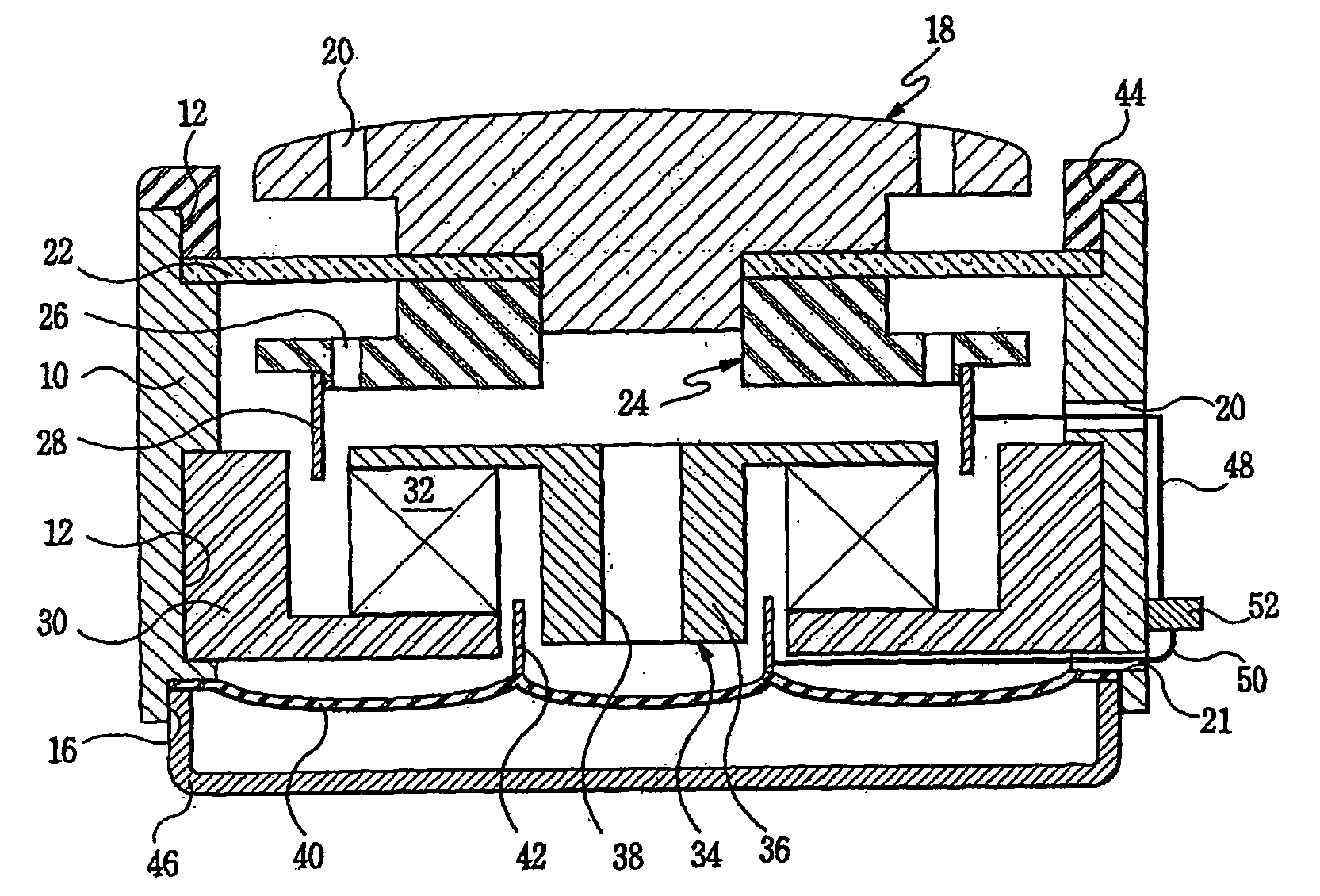
[0035] The bone conduction speaker according to the present invention comprises a body 10 which has a shape of a cylinder with its upper and lower portions opened, as shown in FIG. 1. In the body, two through-holes (not indicated with reference numerals) are formed to connect to an external portion at one side upper wall and one side lower wall.

[0036] A first groove 12 is formed at the upper portion of the body 10, a second groove 14 is formed at the central portion of the body 10, and a third groove 16 is formed at the lower portion of the body 10.

[0037] In addition, the body 10 is constructed with a plastic material for sub-miniaturization. A connection terminal 52 to which an electrical signal is applied from the exterior is formed at a predetermined outer side portion of the body 10.

[0038] A mastoid 18 which is made of a plastic material is formed on the upper portion of the body 10. The lower diameter of the mastoid 18 is smaller that is upper diameter thereof. The vibrating ...

second embodiment

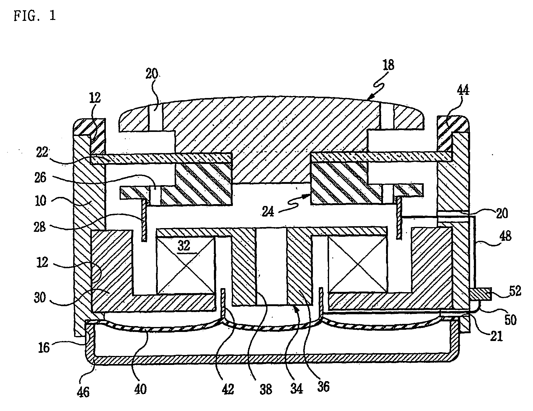
[0065]FIG. 2 is a cross sectional view for illustrating a bone conduction speaker according to the present invention. In FIG. 2, the same parts as those of FIG. 1 are indicated as the same reference numerals, and the description of the same parts and their operations are omitted.

[0066] The bone conduction speaker according to the second embodiment of the present invention is characterized in that the howling preventing hole 38 formed at the protrusion 36 of the yoke 34 is closed, and also, a plurality of acoustic holes 54 are added to the speaker protective cap 46, as shown in FIG. 2.

[0067] Therefore, by a certain physical force F generated around the ring type magnet 32 in accordance with the electrical signal input of the electrical signal input unit, the vibrating coil 28 is moving upwardly and downwardly. By the movement of the vibrating coil 28, acoustic vibrating plate 40 which is fixed at the third groove 16 of the body 10 and made of an elastic material is vibrated. The sou...

third embodiment

[0069] The mobile phone has a main body portion 84 and a cover 86 and further comprises the bone conduction speaker 80 using a vibrating plate according to the present invention. In the mobile phone, the bone conduction speaker 80 is provided at the inner side of the upper end portion of the cover 86 of the mobile phone, so that the user can hear the sound by the vibrational hearing function and the acoustic hearing function simultaneously. Furthermore, in the case the bone conduction speaker is provided to the mobile phone, as shown in FIG. 4, the hole 82 is formed in the outer enclosure of the cover 86, so that the sound emitted through acoustic holes 54 can be heard in the exterior.


PUM


Abstract

The present invention relates to a bone conduction speaker using a vibrating plate. The bone conduction speaker using a vibrating plate according to the present invention is characterized comprises: a body having a shape of a cylinder with an upper portion and a lower portion opened; a mastoid having a lower diameter and a upper diameter, wherein the lower diameter is relatively smaller than the upper diameter; a vibrating late being inserted to a lower portion of the mastoid to close an upper opening portion of the body, wherein the vibrating plate is made of an elastic material; an auxiliary vibrating plate being inserted to a lower portion of the mastoid under the vibrating plate which is inserted to the mastoid; a vibrating coil being attached on a lower side of the auxiliary vibrating plate; a speaker plate being fixed at an inner central portion of the body having the shape of the cylinder, wherein a central hole is provided at the central portion of the speaker plate; a ring type magnet being fixed on the speaker plate; a yoke, wherein an edge portion of the yoke is fixed on the ring type magnet and a central portion of the yoke has a protrusion which protrudes in the inside direction of the central hole of the speaker plate; an acoustic vibrating plate being fixed at a lower portion of the body to close a lower plane of the body; an acoustic coil being fixed on the acoustic vibrating plate and being inserted between the ring type magnet and the yoke; and an electrical signal input unit for applying a predetermined electrical signal to at least one of the vibrating coil and acoustic coil.

Description

TECHNICAL FIELD [0001] The present invention relates to a bone conduction speaker by using a vibrating plate and a mobile phone having the bone conduction speaker, and more specifically, to a two-way bone conduction speaker having an acoustic speaker function in which a sound wave transmitted by a vibration of air vibrates a tympanic membrane of a human body and stimulate an auditory nerve to facilitate the hearing of the sound, thereby being capable of directly vibrating skull bone and stimulating the auditory nerve, so that the sound can be heard and a mobile phone having the bone conduction speaker. BACKGROUND ART [0002] Generally, a sound that is heard by human beings is a wave. The sound wave that is transmitted to the ears of the human beings vibrates the air molecules within the ears. The movement of the molecules, in turn, vibrates the tympanic membrane, that is, eardrum, so that the human beings can hear the sound. [0003] The sound wave entering the external ears of the hum...

Claims


Application Information

Patent Timeline
IPC IPC(8): H04R25/00H04M1/03H04R1/00H04R1/10H04R9/06
CPCH04M1/03H04R2460/13H04R2400/03H04R9/06H04R1/00
Inventor LEE, OUG-KIKIM, JOO-BAE
Owner LEE OUG KI
Why Eureka
Try Eureka