Intervertebral implant

Active Publication Date: 2006-11-23
SCHWAB FR J
View PDF20 Cites 140 Cited by
  • Summary
  • Abstract
  • Description
  • Claims
  • Application Information

AI Technical Summary

Benefits of technology

[0005] The present invention relates to an intervertebral implant for separating an upper vertebra and a lower vertebra. The implant comprises an upper mount having a first surface sized and shaped for mounting on the upper vertebra and a second surface opposite the first surface. The implant also includes a lower mount having a first surface sized and shaped for mounting on the lower vertebra and a second surface opposite the first surface.

Problems solved by technology

Disease, injury, surgery and spinal degeneration can adversely affect the normal function of the intervertebral disc and the complex interrelationship between adjacent vertebrae of the spinal column.
Sometimes pain results from diseased, injured or degenerated discs.
Because the spinal column is frequently moved, resulting pain can occ

Method used


Image

  • Intervertebral implant
  • Intervertebral implant
  • Intervertebral implant

Examples


first embodiment

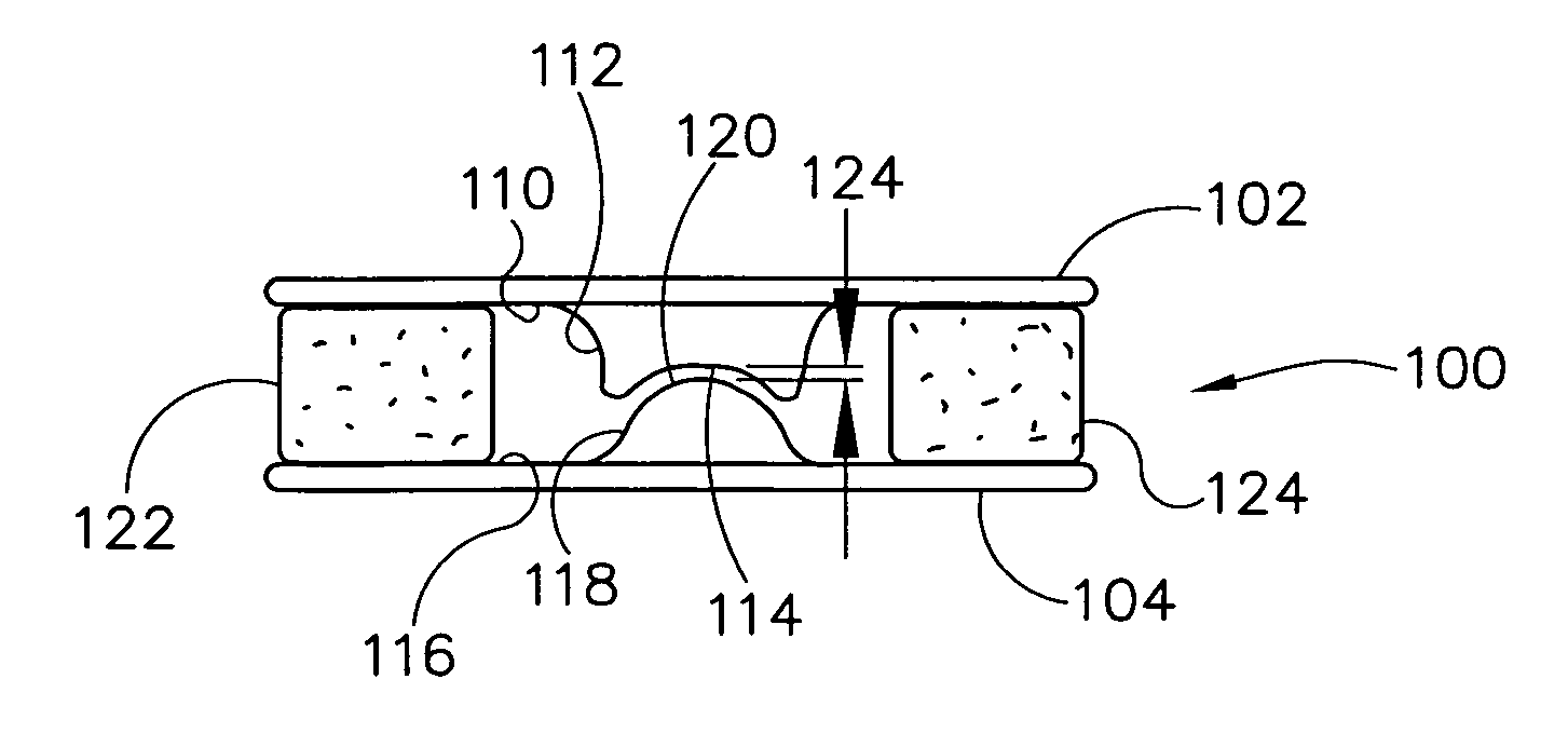
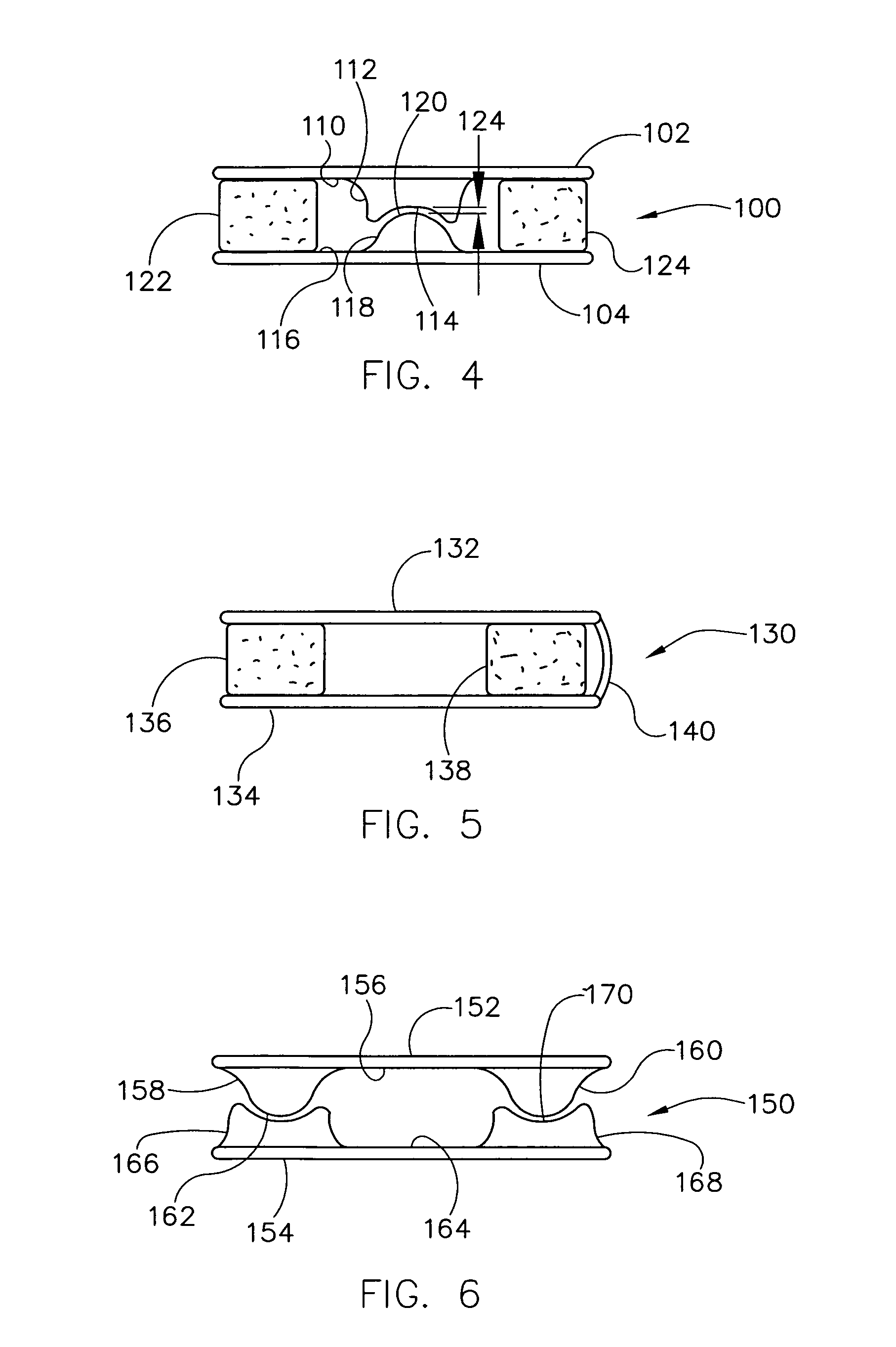
[0044] Referring to FIG. 4, an intervertebral implant of a first embodiment is designated in its entirety by the reference number 100. The implant 100 includes an upper plate or mount 102 and a lower plate or mount 104. The upper plate 102 includes a lower face 110 and a protrusion 112 having a concave lower end 114 extending downward from the lower face. The lower plate 104 includes an upper face 116 and a protrusion 118 having a convex upper end 120 extending upward from the upper face. The concave end 114 of the upper plate protrusion 112 receives the convex end 120 of the lower plate protrusion 118. The concave end 114 and the convex end 120 have complementary shapes (e.g., similarly sized spherical shapes) allowing the upper and lower plates 102, 104 to pivot with respect to each other. Although the concave end 114 and the convex end 120 may have other radii without departing from the scope of the present invention, in one embodiment the concave end has a radius of between abou...

tenth embodiment

[0056]FIGS. 13-15 illustrate an implant of a tenth embodiment, generally designated by 270. The implant 270 includes two upper plates 272, 274 overlapped at one end and arranged in a V-shape as shown. The implant 270 also includes two lower plates 276, 278 overlapped at one end and also arranged in a V-shape as shown. Although the upper and lower plates 272, 274, 276, 278 may be overlapped at other ends without departing from the scope of the present invention, in one embodiment, the plates are overlapped at their forward ends. A forward compressible element 280 is positioned between the upper and lower plates 272, 280. Rearward compressible elements 282, 284 are positioned between respective rearward ends of the upper and lower plates as shown. The plates may be fastened together using conventional means such as interlocking parts, riveting or brazing. Although the upper plates 272, 274 and lower plates 276, 278 may be arranged to form other included angles, in one embodiment, both...


PUM


Abstract

An intervertebral implant for separating an upper vertebra and a lower vertebra. The implant includes an upper mount having a first surface sized and shaped for mounting on the upper vertebra and a second surface opposite the first surface. The implant includes a lower mount having a first surface sized and shaped for mounting on the lower vertebra and a second surface opposite the first surface. The implant includes an element positioned between the upper mount and the lower mount spacing the first surface of the upper mount from the first surface of the lower mount by a predetermined distance. The element is configured to permit the upper mount to pivot relative to the lower mount. The element allows the upper vertebra to pivot relative to the lower vertebra while maintaining spacing between the upper vertebra and the lower vertebra.

Description

CROSS-REFERENCE TO RELATED APPLICATIONS [0001] This application claims priority from U.S. Provisional Patent Application No. 60 / 681,793 filed May 17, 2005, entitled, “Ensemble of Devices and Methods for Dynamic Posterior Spinal Stabilization”, and U.S. Provisional Patent Application No. 60 / 700,197 filed Jul. 18, 2005, entitled, “Posteriorly Placed Intervertebral Dynamic Implant”. Both of these applications are incorporated by reference.BACKGROUND [0002] The present invention relates to implants and, more particularly, to intervertebral implants. [0003] Vertebrae of the human spine are arranged in a column with one vertebra positioned on top of the next. An intervertebral disc is positioned between each vertebrae pair to provide a cushion between the adjacent vertebrae and transmitting forces. The discs permit movement between vertebra so the column can twist, bend, stretch and compress. Disease, injury, surgery and spinal degeneration can adversely affect the normal function of the ...

Claims


Application Information

Patent Timeline
IPC IPC(8): A61F2/44
CPCA61B17/7067A61F2310/00029A61F2/442A61F2/4425A61F2002/30176A61F2002/30179A61F2002/30441A61F2002/30448A61F2002/30563A61F2002/30649A61F2002/30665A61F2002/30841A61F2220/0041A61F2220/005A61F2230/0054A61F2230/0058A61F2310/00017A61F2310/00023A61F2/4405A61F2002/30433
Inventor SCHWAB, FRANK JOHANN
Owner SCHWAB FR J
Why Eureka
Try Eureka