Thermoelectric device with surface conforming heat conductor

a heat conductor and thermoelectric device technology, applied in the direction of thermoelectric device with peltier/seeback effect, thermoelectric device junction materials, electrical apparatus, etc., can solve the problem of limited useful life of thermoelectric devices, and achieve the effect of low cost and ease of installation

Inactive Publication Date: 2006-11-30
HI Z TECH
View PDF5 Cites 31 Cited by
  • Summary
  • Abstract
  • Description
  • Claims
  • Application Information

AI Technical Summary

Benefits of technology

[0010] In preferred embodiments a number of thermoelectric units are contained in a cover useful for wrapping around hot or cold pipes or covering other hot or cold items. This embodiment is designed for low cost and ease of installation. Another preferred type of embodiment of this invention is a quick attachment thermoelectric device. The device includes at least one permanent magnet for providing a magnetic attractive force to hold a surface of a thermoelectric module against the hot or cold surfaces. In this preferred embodiment the module is utilized to provide electric power to power a transmitter to transmit information regarding the location of the motor vehicle to which it is attached. Standard thermoelectric modules available on the market can be utilized. Another preferred embodiment is designed especially to provide electric power to low use instruments at locations remote from utility electric power. This is a relatively high efficiency device in which the bottom of a metal pedestal is made to conform to the hot or cold surface. The thermoelectric module is held in compression between the pedestal and a fin unit and the pedestal is compressed against the hot or cold surface with a worm drive pipe clamp.

Problems solved by technology

These devices are typically powered by batteries so that their useful life is limited.

Method used


Image

  • Thermoelectric device with surface conforming heat conductor
  • Thermoelectric device with surface conforming heat conductor
  • Thermoelectric device with surface conforming heat conductor

Examples


first preferred embodiment

Quick Attaching Thermoelectric Device

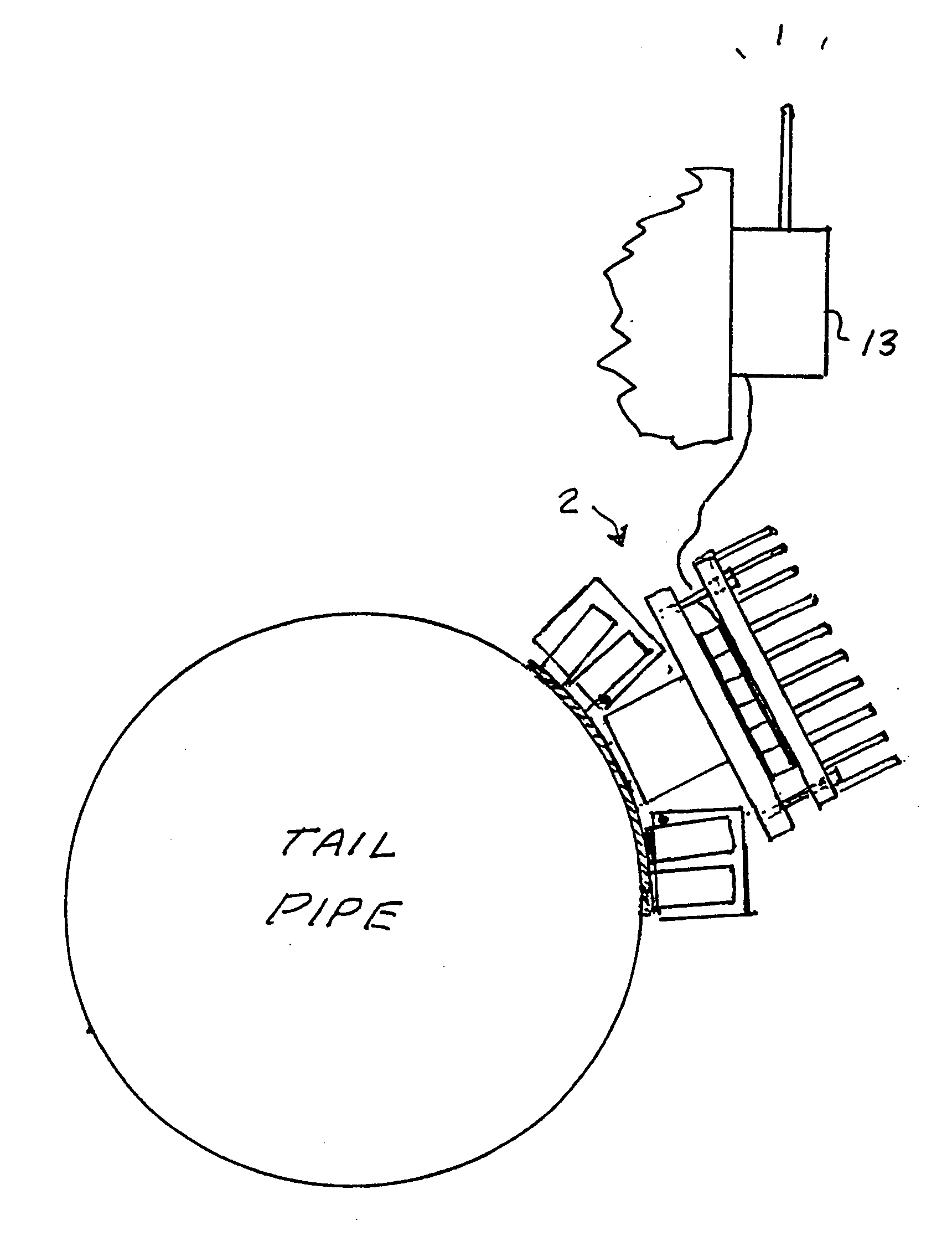
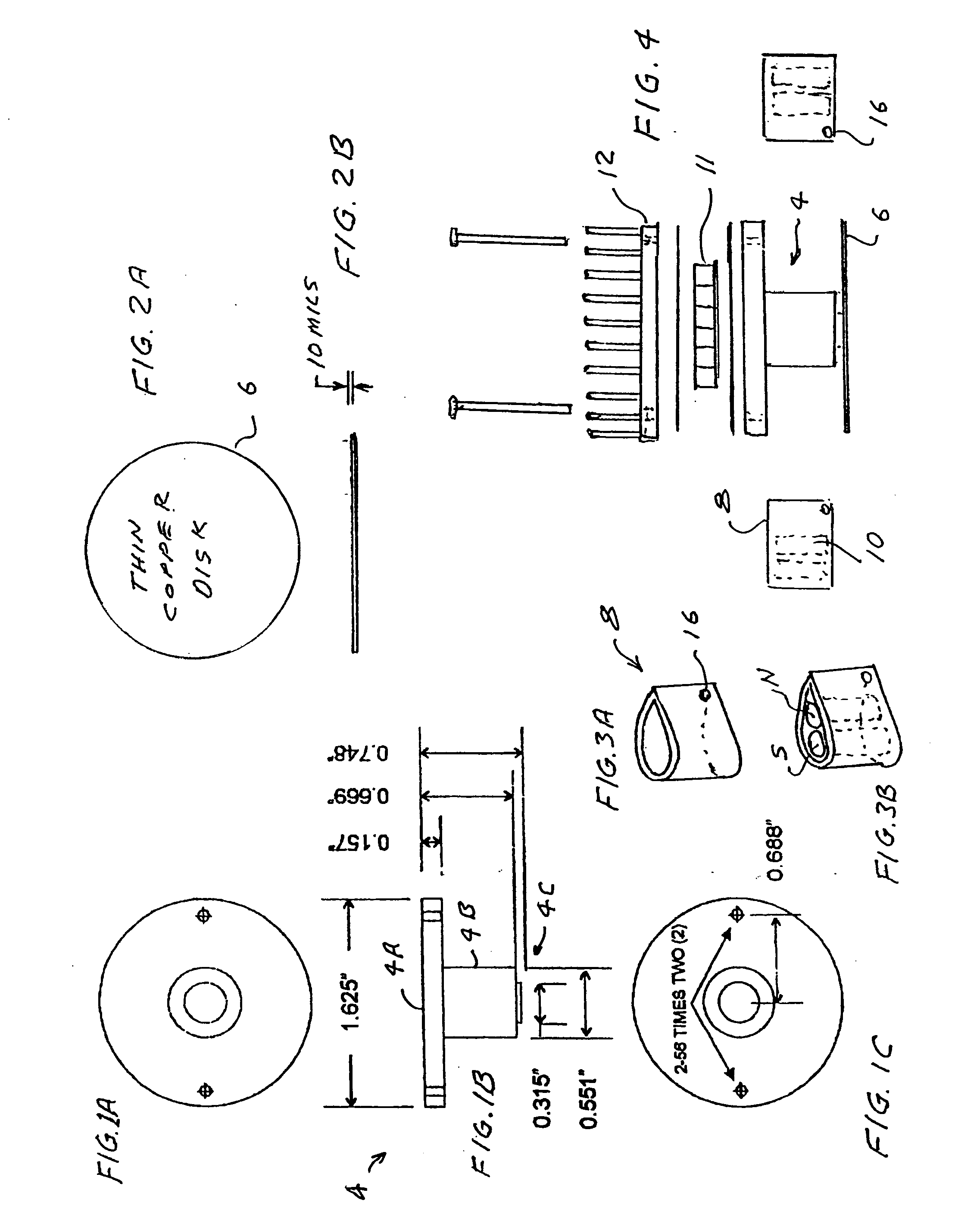
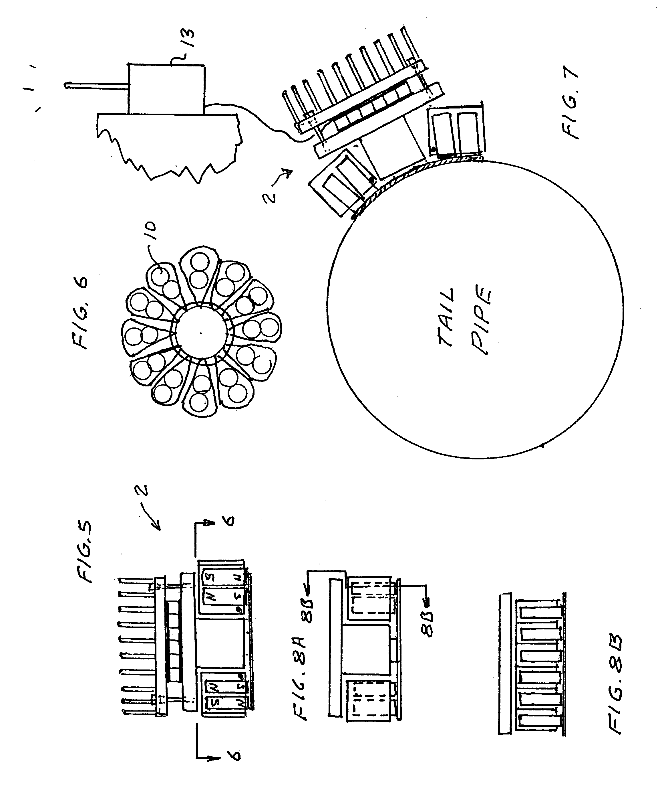
[0025]FIGS. 1A through 7 show the basic features of a first preferred embodiments of the present invention. In this embodiment a thermoelectric generator is attached to a cylindrical steel tail pipe of a motor vehicle with the magnetic force of a plurality of magnets that compresses a thin flexible high heat conducting element against the tail pipe. Preferably, the thin flexible high heat conducting element is a thin copper disk and it is braised to a thin bottom portion of a copper pedestal that has a wider flat upper portion. The wider flat upper portion is the heat source of a thermoelectric module that is compressed between an aluminum fin unit functioning as a heat sink and the flat upper portion of the pedestal. Insulating wafers on both the hot and cold sides to the thermoelectric module provide electrical insulation of the module from the copper pedestal and the finned heat sink. Heat conducting grease is used to improve thermal conducti...

second preferred embodiment

Quick Attaching with Rectangular Bottom

[0027] A second preferred embodiment of the present invention is shown in FIGS. 8A and 8B. This unit is exactly the same as the generator of the first preferred embodiment except the thin bottom part of pedestal 4 is rectangular rather than circular. This second preferred embodiment is useful for attachment to flat and cylindrical surfaces but would not attach very well to spherical surfaces. Also, when attaching it to cylindrical surfaces care must be taken to line it up with the axis of the cylindrical surface. It should attach very well however to tail pipes and mufflers of motor vehicles.

third preferred embodiment

Thermoelectric Blanket with Top and Bottom Copper Foils

[0028]FIGS. 9 through 13 describe a preferred embodiment in which a number of thermoelectric units are contained in a cover 30 as shown in FIG. 13 useful for wrapping around hot or cold pipes or covering other hot or cold items. A particular preferred embodiment is a cover 6 inches wide with thermoelectric modules spaced at 5-inch centers. Top and a bottom 6 inch wide 10 mil thick Kapton sheets 32 form the structure of the cover. The sheets may be any length, but in this particular embodiment they are about 60 feet. Three-inch diameter holes 34 are cut in the along a center line of both top and bottom sheets at 5-inch centers. Top pedestal 36 and bottom pedestal 38 each about ¼ inch high and having a wide diameter part 40 and a narrow diameter part 42 are each braised at its narrow surface to a thin flexible heat conductor 44A and 44B, preferably 10 mil thick 4-inch diameter copper foil. The foils are then thermally fused to co...


PUM


Abstract

A quickly attachable electric generator device for producing electric power from surfaces of hot or cold pipes. The invention provides a thermoelectric unit which includes a pedestal comprised of a material with high thermal conductivity on which a thermoelectric module is located. The pedestal includes a heat transfer element made to conform to a hot or cold cylindrical surface. The module also includes a module-to-air heat transfer element and the thermoelectric module is compressed between the air-to-module element and the pedestal. This element is referred to as a heat sink when energy is extracted from a hot surface and is referred to as a heat source when energy is flowing from the air and a cold surface. In preferred embodiments the heat transfer element is a thin flexible heat conductor that conforms to the hot or cold surface of various shapes and serves as a heat transfer conduit to transfer heat to or from a rigid portion of the pedestal. Electric energy is generated from the heat flowing through the module.

Description

[0001] The present invention relates to thermoelectric devices and in particular techniques for producing electric power from existing heat sources such as hot pipes. This application is a continuation in part of Ser. No. 11 / 138,741. filed May 25, 2005.BACKGROUND OF THE INVENTION [0002] A well-known use for thermoelectric devices is for the extraction of electric power from waste heat. For example, U.S. Pat. No. 6,527,548 discloses a self powered space heater for a truck in which heat energy for the heater is used to power electric components of the heater plus charge a battery. In U.S. Pat. No. 6,053,163 heat from a stovepipe is used to generate electricity. U.S. Pat. No. 6,019,098 discloses a self-powered furnace. Various types of thermoelectric modules are available. A very reliable thermoelectric module with a gap-less egg-crate design is described in U.S. Pat. Nos. 5,875,098 and 5,856,210. U.S. Pat. No. 6,207,887 discloses a miniature milli-watt thermoelectric module useful in ...

Claims


Application Information

Patent Timeline
Patent Type & Authority Applications(United States)
IPC IPC(8): H01L35/30H10N10/00H10N10/13
CPCH01L35/00H01L35/30H01L35/22H10N10/00H10N10/855H10N10/13H10N10/8556
Inventor HILLER, NATHAN DAVIDBASS, JOHN CLAUDE
Owner HI Z TECH
Why Eureka
Try Eureka