Tandem rotor wing and tandem fixed wing aircraft

a technology of tandem fixed wings and rotor wing wings, which is applied in the field of aircraft, can solve the problems of large load, difficult transition from vertical flight to forward flight while carrying heavy loads, and large load

Active Publication Date: 2006-11-30
YAHOO INC +1
View PDF10 Cites 44 Cited by
  • Summary
  • Abstract
  • Description
  • Claims
  • Application Information

AI Technical Summary

Benefits of technology

[0005] The present invention relates to aircraft comprising an airframe having a fuselage extending longitudinally between a forward end and an aft end opposite the forward end. The aircraft further includes at least two fixed wing sets extending laterally from the fuselage wherein a first fixed wing set of the fixed wing sets is positioned closer to the forward end of the fuselage than a second fixed wing set of the fixed wing sets and the second fixed wing set is positioned closer to the aft end of the fuselage than the first fixed wing set. In addition, the aircraft includes a power plant mounted on the airframe and at least two rotor wings rotatably mounted on the airframe. Each rotor wing has a plurality of blades extending outward from a central hub to blade tips. The blade tips of the rotor wings circumscribe respective circles centered on the corresponding central hubs during rotation of the rotor wings and each fixed wing set is located generally below the circumscribed circle of only one of the rotor wings. Also, the aircraft includes a rotation mode in which at least one of the rotor wings is rotated by the power plant and a fixed mode in which the rotor wings are locked to prevent rotation thereof.

Problems solved by technology

Reliably carrying large loads, such as loads weighing more than about 2 tons, using V / STOL aircraft has traditionally been problematic due to vertical thrust and aircraft control limitations.
Even with two rotor wings, however, transitioning from vertical flight to forward flight while carrying heavy loads can prove problematic due to insufficient pitch control.
A fixed wing set located about halfway along the length of the fuselage, i.e., in the region of a cargo bay, may provide lift and some pitch control, but it does not contribute enough pitch control for tandem rotor wing aircraft to simultaneously slow and stop both rotor wings while carrying a heavy load.
Thus, when transitioning from vertical to forward flight, the rotor wings of tandem rotor heavy lift aircraft cannot be stopped simultaneously because one rotor is needed to provide pitch control while the other rotor is being stopped.
Another problem of traditional tandem rotor wing aircraft is a tendency for the blades of overlapping rotor wings to contact.
The blade contact problem is often increased for heavy lift aircraft because the increased forces encountered by the blades cause the blades of the respective rotor wings to deflect by larger amounts from designated planes of rotation and into the paths of each other.

Method used


Image

  • Tandem rotor wing and tandem fixed wing aircraft
  • Tandem rotor wing and tandem fixed wing aircraft
  • Tandem rotor wing and tandem fixed wing aircraft

Examples


Embodiment Construction

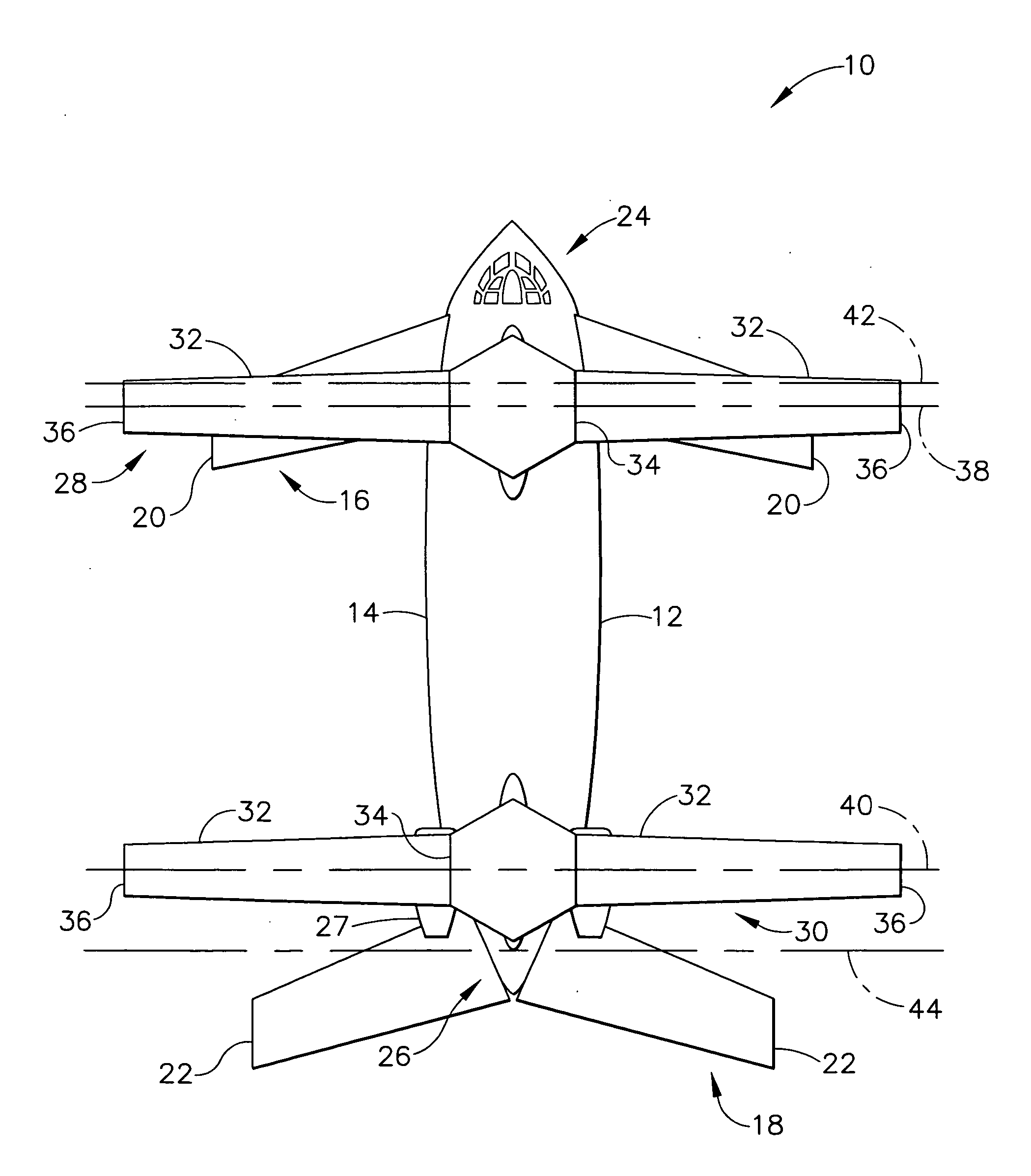
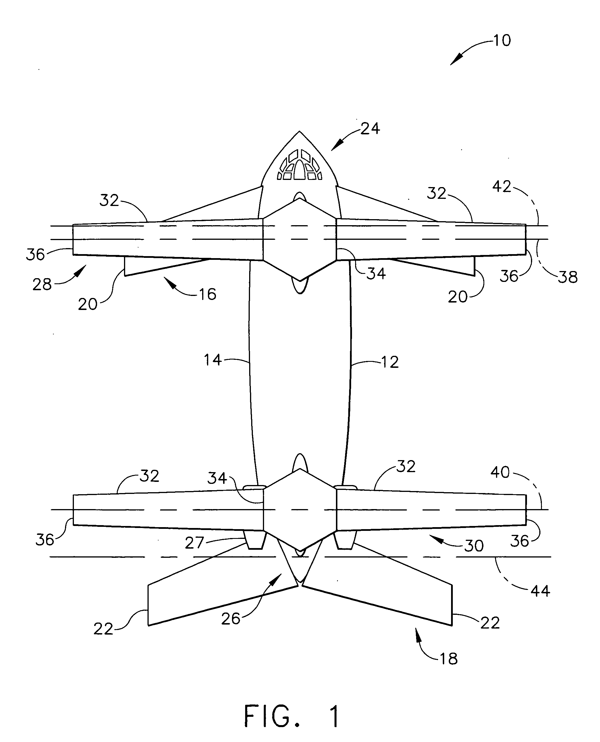
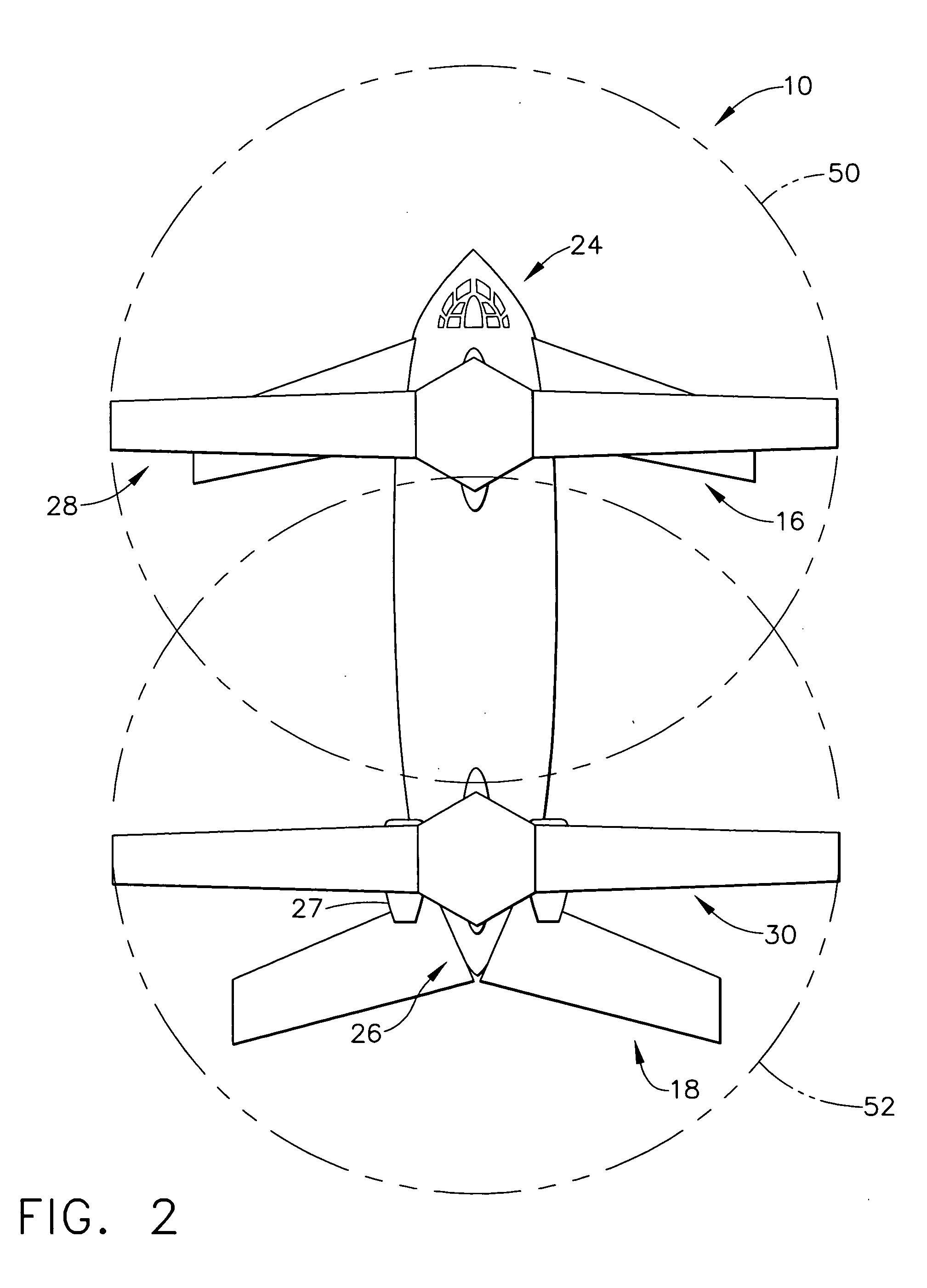
[0017] The present invention relates to aircraft, and more particularly to heavy lift vertical and short take-off aircraft having at least two rotor wings and at least two fixed wing sets. Referring now to the figures, and more particularly to FIG. 1, an aircraft according to a first embodiment of the present invention is designated in its entirety by reference number 10. The aircraft 10 has an airframe 12 including a fuselage 14 extending longitudinally and two fixed wing sets 16, 18 extending laterally from the fuselage. Although two fixed wing sets 16, 18 are shown, the airframe 12 can include more than two fixed wing sets without departing from the scope of the present invention. Although the fixed wing sets 16, 18 may have other wingspans without departing from the scope of the present invention, in one embodiment one of the fixed wing sets 16 has a wingspan extending between wingtips 20 of between about 40 feet and about 50 feet and the other fixed wing set 18 has a wingspan e...


PUM


Abstract

Aircraft comprising an airframe having a fuselage, at least two fixed wing sets. A first fixed wing set of the fixed wing sets is positioned closer to a forward end of the fuselage than a second fixed wing set and the second fixed wing set is positioned closer to the aft end of the fuselage than the first fixed wing set. The aircraft includes a power plant mounted on the airframe and at least two rotor wings rotatably mounted on the airframe. Each rotor wing has a plurality of blades extending outward from a central hub to blade tips. The blade tips of the rotor wings circumscribe respective circles centered on the corresponding central hubs during rotation of the rotor wings and each fixed wing set is located generally below the circumscribed circle of only one of the rotor wings. The aircraft includes a rotation mode and a fixed mode.

Description

BACKGROUND OF THE INVENTION [0001] The present invention relates to aircraft capable of vertical and short take-off and landing and, more particularly, to aircraft capable of such flight through the use of fixed wing sets and rotor wings that can be selectively stopped to act as fixed wings. [0002] Aircraft designed to allow vertical and short take-off and landing, hovering, full forward flight, and transitional flight have existed since about the middle of the twentieth century. These vehicles are often referred to as dual mode or V / STOL aircraft because of their vertical and / or short take-off and landing capabilities. Traditional V / STOL aircraft have been designed to carry relatively small payloads. Reliably carrying large loads, such as loads weighing more than about 2 tons, using V / STOL aircraft has traditionally been problematic due to vertical thrust and aircraft control limitations. [0003] One method of providing vertical thrust to an aircraft is by using a single rotor wing ...

Claims


Application Information

Patent Timeline
Patent Type & Authority Applications(United States)
IPC IPC(8): B64C27/22
CPCB64C27/08B64C39/08B64C27/24
Inventor SVOBODA, CHARLES R. JR.
Owner YAHOO INC
Why Eureka
Try Eureka