

Headlight beam control system and headlight beam control method
- Summary
- Abstract
- Description
- Claims
- Application Information
AI Technical Summary
Benefits of technology
Problems solved by technology
Method used
Image

Examples
Embodiment Construction
[0016] Preferred embodiments of the present invention are described below with reference to the accompanying drawings.
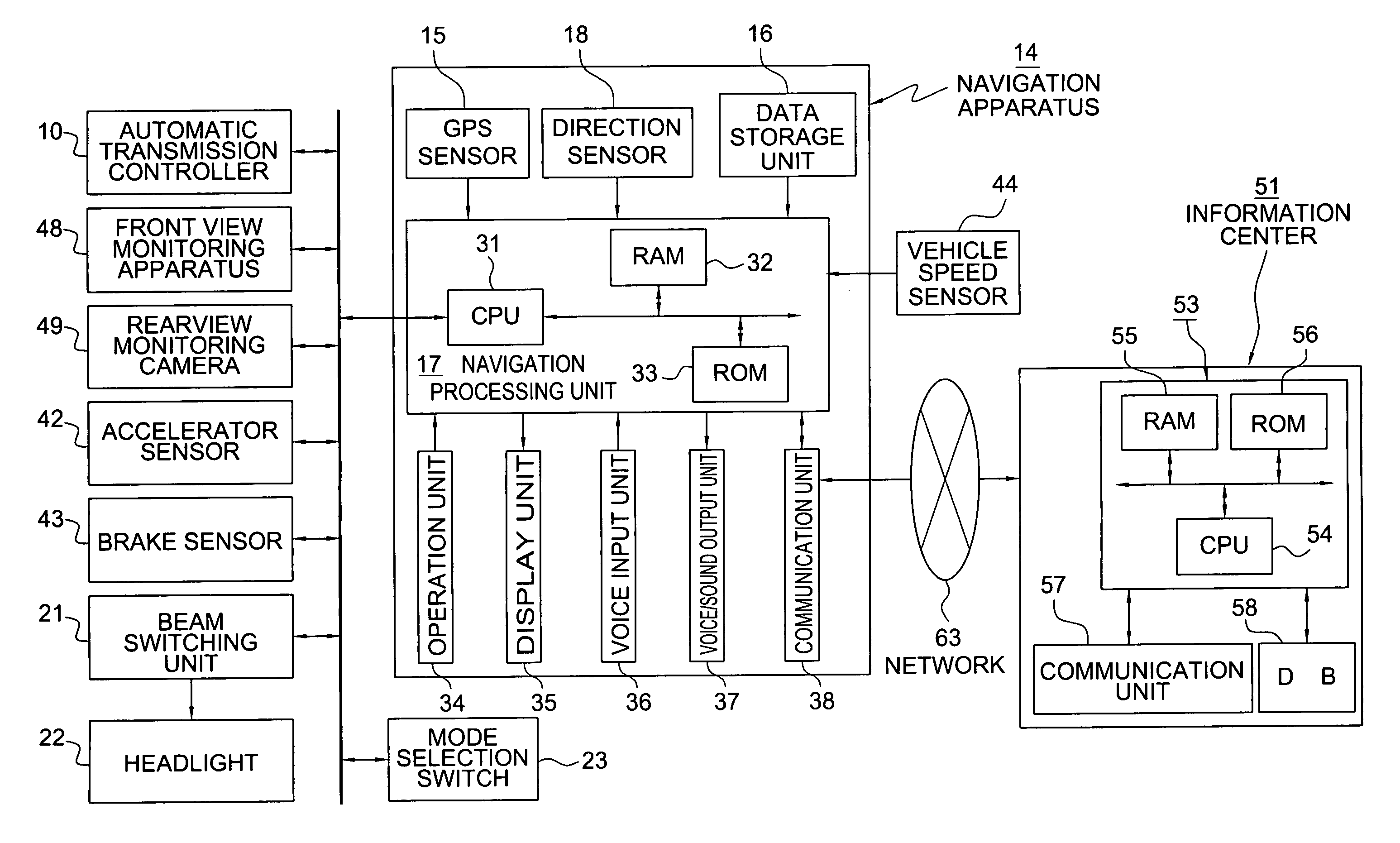
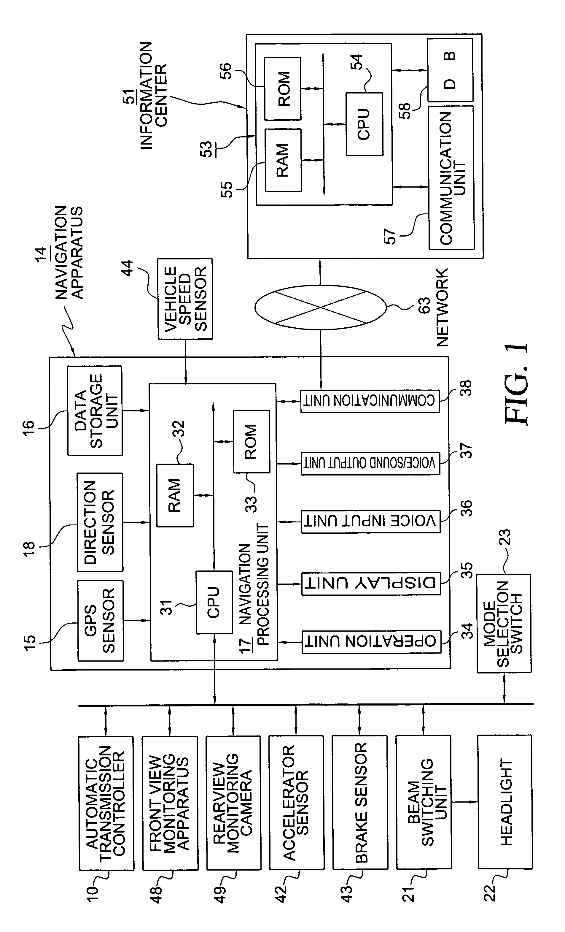
[0017]FIG. 1 is a block diagram showing a navigation system according to an embodiment of the present invention.
[0018]FIG. 1, shows an automatic transmission controller, i.e. a power train controller, connected to an automatic transmission (not shown) for controlling the automatic transmission.
[0019] An on-board information terminal 14, e.g. navigation apparatus, is connected to an information center 51 (an information provider) via a network 63. Thus, the navigation system includes the automatic transmission controller 10, the navigation apparatus 14, the network 63, and the information center 51.
[0020] The navigation apparatus 14 includes a GPS sensor 15 serving as a current position detector for detecting the current position of the user's vehicle, a data storage unit 16 in which map data and other various kinds of information are stored, a navigation processi...
PUM
 Abstract
Description
Claims
Application Information