Inkjet Recording Apparatus

a recording apparatus and inkjet technology, applied in the direction of printing, other printing apparatus, etc., can solve the problems of deteriorating the quality of the image at the outline, and achieve the effect of improving the print quality of the imag

Inactive Publication Date: 2006-11-30
BROTHER KOGYO KK
View PDF0 Cites 2 Cited by
  • Summary
  • Abstract
  • Description
  • Claims
  • Application Information

AI Technical Summary

Benefits of technology

[0013] It is an object of this invention to provide an inkjet recording apparatus which can

Problems solved by technology

Hence, a variation in volume of ink droplets significantly affects the uniformity in shape, size and density of the dots

Method used


Image

  • Inkjet Recording Apparatus
  • Inkjet Recording Apparatus
  • Inkjet Recording Apparatus

Examples


first embodiment

[0053] There will be described an inkjet recording apparatus according to the invention, by referring to FIGS. 1-5 and FIGS. 7A-7C.

[General Structure of the Inkjet Recording Apparatus]

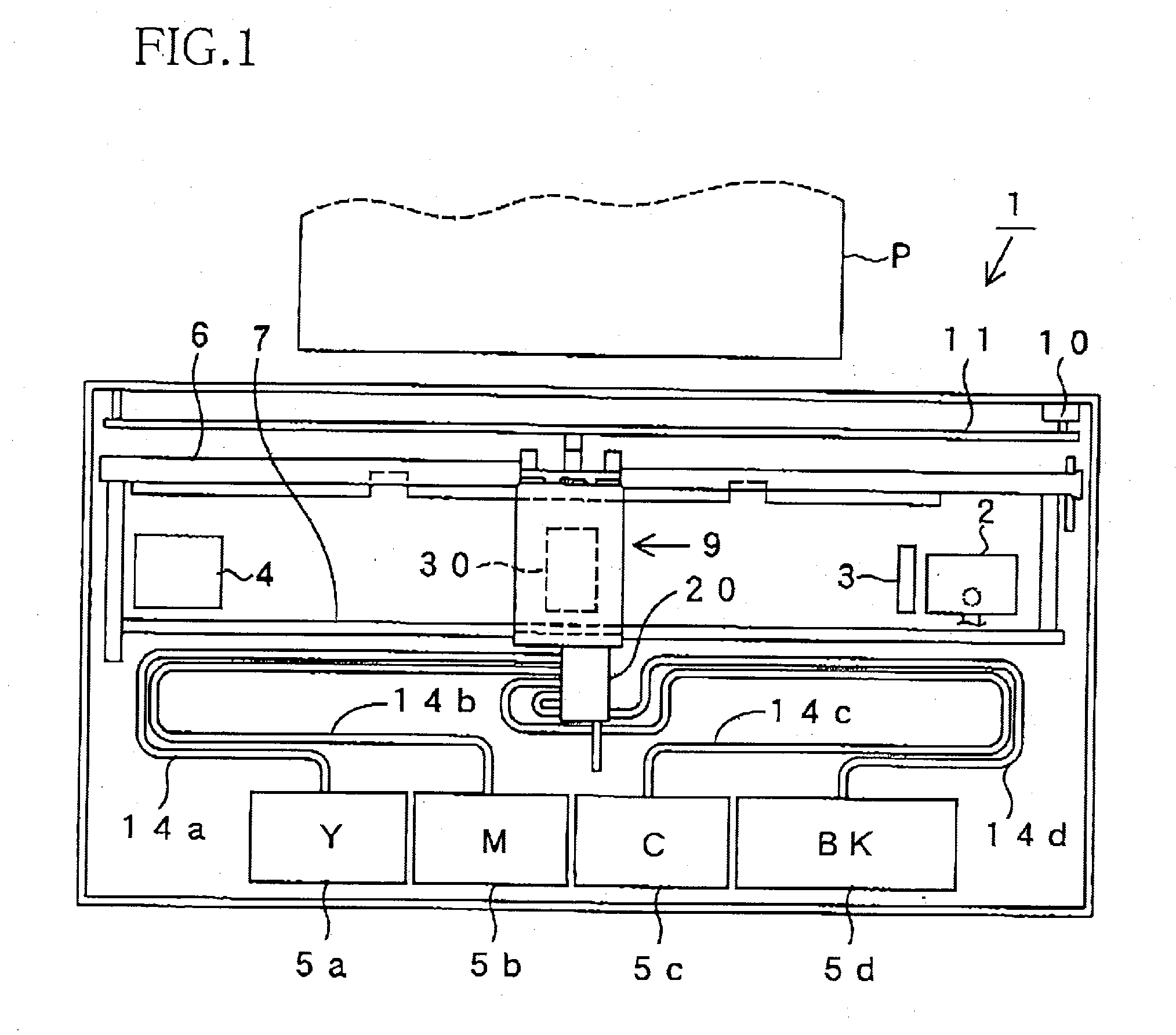
[0054] Initially, a general structure of the inkjet recording apparatus is described with reference to FIG. 1, which is a schematic plan view of the inkjet recording apparatus.

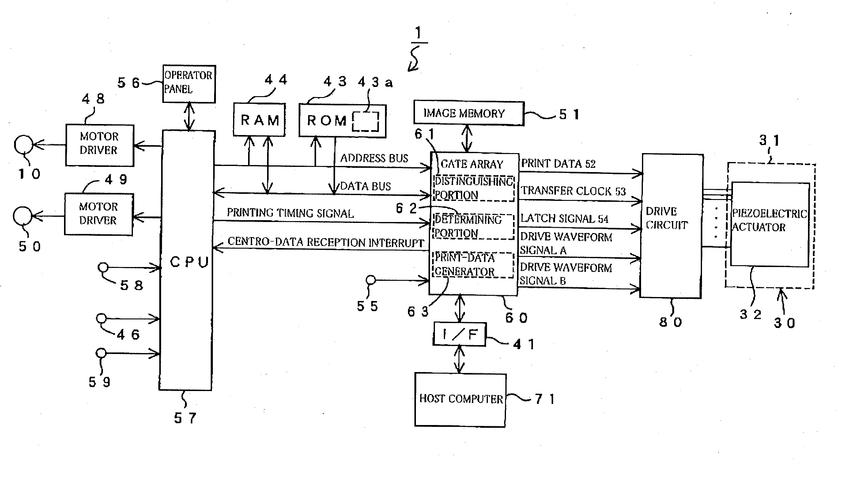
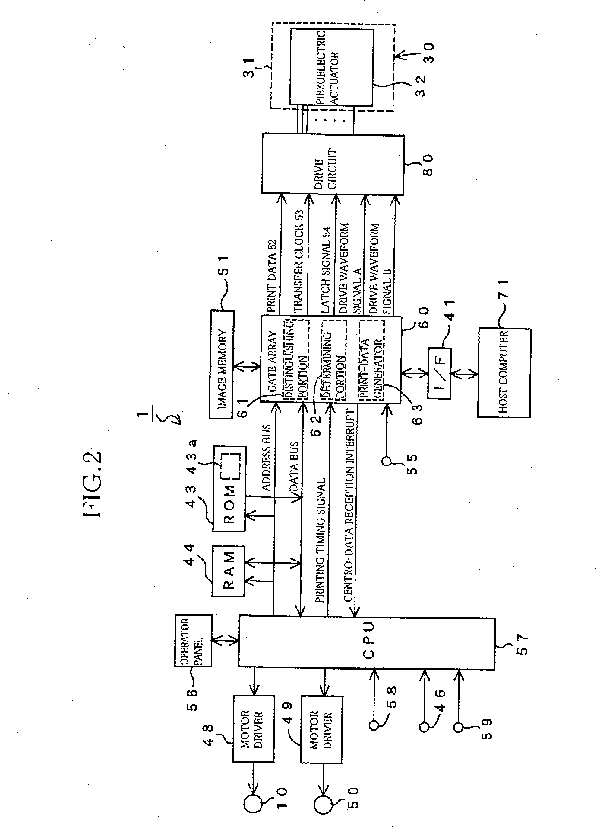
[0055] In the inkjet recording apparatus, which is generally denoted by reference numeral 1, are disposed two guide rods 6, 7 opposite each other. To the guide rods 6, 7 is attached a head holder 9 which serves as a carriage as well as a holder if an inkjet recording head 30 that performs recording of an image on a recording sheet P by ejecting ink droplets therefrom onto the recording sheet P. The recording head 30 includes a mainbody having a plurality of nozzles, a plurality of ink passages communicated with the respective nozzles, and an actuator unit 32 for applying energy for ejecting ink droplets. In this specific exampl...

second embodiment

[0102] There will be now described an inkjet recording apparatus according to the invention, with reference to FIG. 6.

[0103] The inkjet recording apparatus of the second embodiment is characterized by being capable of performing high-quality printing by taking account of change in the viscosity of the ink depending on the environmental temperature.

[0104]FIG. 6 is a flowchart illustrating a print control implemented in the inkjet recording apparatus according to the second embodiment. Only a part of the print control differs from that of the inkjet recording apparatus according to the first embodiment, and except which the structure and function of the apparatus of the second embodiment is identical with the apparatus of the first embodiment. Hence, the elements or parts corresponding to those of the first embodiment will be denoted by the same reference symbols or numerals and description there of is omitted or only briefly illustrated.

[0105] According to the experiment conducted ...


PUM


Abstract

An inkjet recording apparatus including: a recording head movable in a main scanning direction, and including: an ink passage; a nozzle communicated with the passage; and an actuator applying energy to ink in the passage to eject a droplet thereof from the nozzle; a control device outputting a drive waveform signal, while the head is moved in the direction, to drive the actuator, the control device including: a storing portion storing plural kinds of the signals different from one another in the number of the ejected droplets for one dot; and an outputting portion including: a determining portion making at least one of the following determinations, for each particular one of dots printed in series at least in the direction: whether there is a dot printed immediately before the particular dot, and whether there is a dot printed immediately after the particular dot; and a selecting portion selecting one of the kinds of the signals, based on a result of the determination made by the determining portion, and outputting the selected kind of the signal to the actuator; and the selecting portion selecting (i) a first one of the kinds of the signals, when a result of the determination is affirmative, and (ii) a second one of the kinds of the signals, when the result of the determination is negative, the first kind and second king respectively being for ejecting a first number and a second number of the droplet or droplets for the particular dot, the second number being smaller than the first number.

Description

INCORPORATION BY REFERENCE [0001] The present application is based on Japanese Patent Application No. 2005-156067, filed on May 27, 2005, the contents of which is incorporated herein by reference. BACKGROUND OF THE INVENTION [0002] 1. Field of the Invention [0003] The invention relates to an inkjet recording apparatus which includes a nozzle and an actuator, and ejects an ink droplet from the nozzle onto a recording medium by driving the actuator, thereby recording an image or information on the recording medium. [0004] 2. Description of Related Art [0005] As a kind of an inkjet recording apparatus of this type, the publications 1-4 set forth below disclose apparatuses that control printing of dots in order to prevent blurring or spreading of ink that is a phenomenon that when a droplet of ink is ejected onto a recording medium to form a dot on an outline of an image recorded on the recording medium, the ejected ink droplet grows or spreads on the recording medium into a white, non-...

Claims


Application Information

Patent Timeline
IPC IPC(8): B41J29/38
CPCB41J2/04581B41J2/04588B41J29/393B41J2/17509B41J2/04595
Inventor ITO, MASAHARU
Owner BROTHER KOGYO KK
Why Eureka
Try Eureka