
Ramp loading unit and drive having the same

a technology of loading unit and drive, which is applied in the direction of magnetic recording, data recording, instruments, etc., can solve the problems of increasing the cost of texture process, increasing the difficulty of texture processing, and cramming or damage of discs, so as to prevent damage to the ramp and lift the tab, and wide effective recording area

Inactive Publication Date: 2006-11-30
KK TOSHIBA
View PDF4 Cites 18 Cited by
  • Summary
  • Abstract
  • Description
  • Claims
  • Application Information

AI Technical Summary

Benefits of technology

[0008] Accordingly, it is an exemplary object of the present invention to provide a ramp loading unit and a drive having the same, which prevent damages of the ramp and lift tab, and maintain a wide effective recording area on a recording medium.
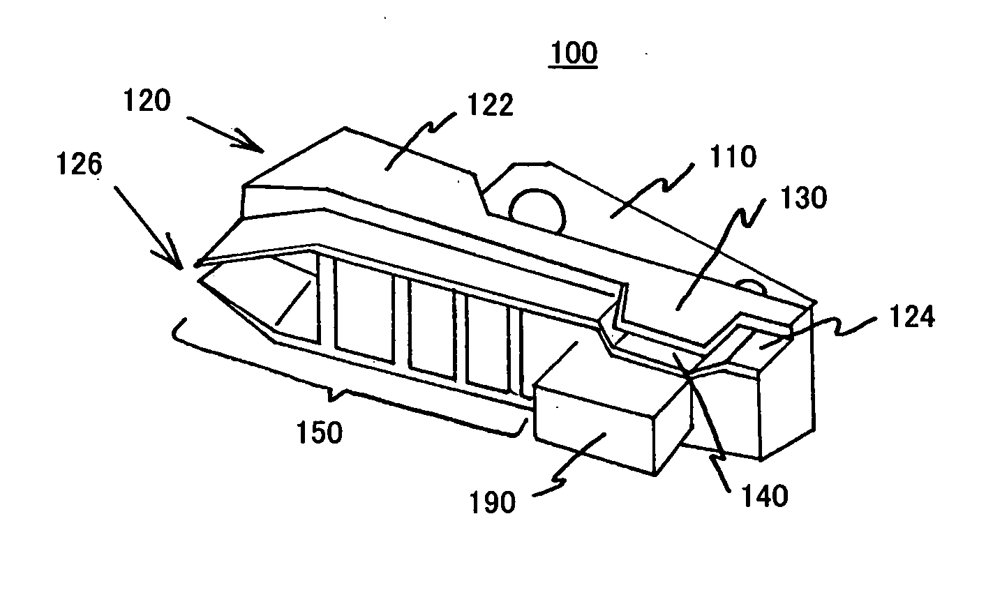
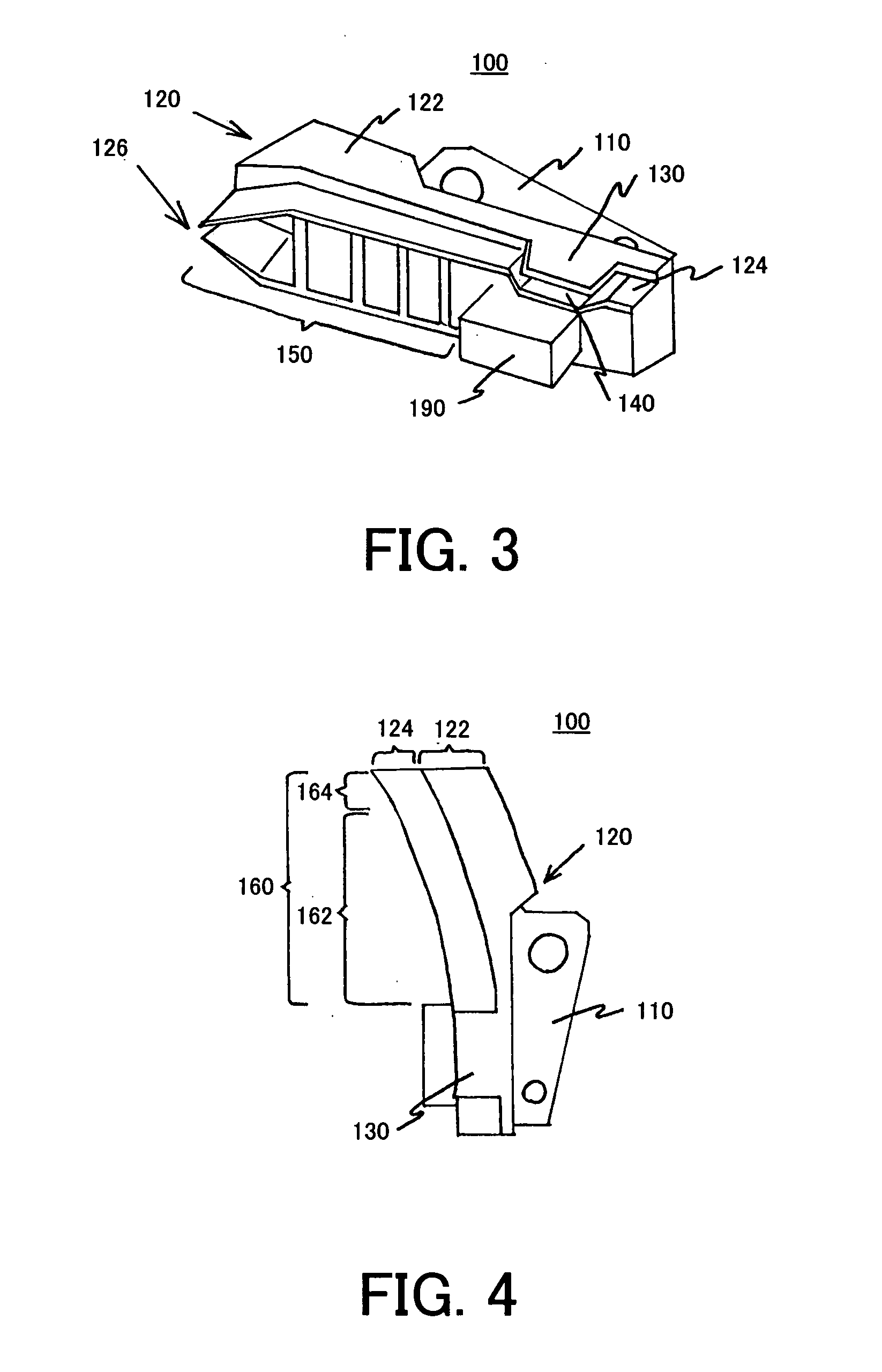
[0009] A ramp loading unit according to one aspect of the present invention includes a holding part that holds, outside a recording medium, a lift tab connected to a suspension that supports a head used to record information in or reproduce the information from the recording medium, and a sliding part to which the lift tab elastically contacts in loading the head onto the recording medium and in unloading the head from the recording medium, wherein the sliding part includes an inclined part that projects at least partially above the recording medium, inclines relative to a surface of the recording medium, and partially changes an inclination angle of the inclined part. According to this ramp loading unit, the partially changing inclination angle of the inclined part makes the horizontal distance of the inclined part shorter than that in the conventional ramp loading unit that maintains the inclination angle constant. As a result, the shorter horizontal distance by which the projected part projects above the recording medium reduces the recording area on the recording medium invaded by the inclined part. In addition, the head can be more quickly loaded onto and unloaded from the recording medium.
[0010] The inclined part may have first and second positions in a direction from the recording medium to the holding part, the first position being closer to the recording medium than the second position, and the inclination angle at the second position being greater than the inclination angle at the first position. The first and second positions are arranged, for example, between a position where the lift tab first contacts the sliding part and a position at which the head cannot record the information in or reproduce the information from the recording medium in unloading the head from the recording medium. This configuration reduces not only the impact when the lift tab contacts the inclined part in unloading, but also the projection amount by which the inclined part projects above the recording medium. Preferably, the sliding part has the inclination angle of about 0° at a position where the lift tab first contacts the sliding part in unloading the head from the recording medium. This configuration reduces the impact when the lift tab contacts the inclined part in unloading. The inclined part forms a line, a curve or a combination of plural curves when projected onto a plane parallel to a longitudinal direction of the inclined part. The inclined part preferably has a maximum inclination angle of 50° or smaller. When the inclined part of the ramp has a greater inclination angle, the inclined part contacts the edge of the lift tab and prevents smooth loading and unloading.
[0011] A ramp loading unit according to another aspect of the present invention includes a holding part that holds a lift tab outside a recording medium, the lift tab being inclined relative to a surface of the recording medium and connected to a suspension that is rotatable around a shaft and supports a head used to record information in or reproduce the information from the recording medium, and a sliding part to which the lift tab elastically contacts in loading the head onto the recording medium and in unloading the head from the recording medium, wherein the sliding part when projected onto a plane perpendicular to the shaft is so shaped that a locus of a contact position between the lift tab and the sliding part when projected onto the plane shifts from a circle whose center is located at the shaft when the locus starts with a position where the lift tab first contacts the sliding part. According to this ramp loading unit, the position where the lift tab contacts the sliding part displaces on the lift tab. Therefore, a properly set inclination of the lift tab can make shorter the horizontal distance of the projection of the sliding part above the recording medium than that in the conventional ramp loading apparatus that fixes, on the lift tab, the contact position between the lift tab and the sliding part. As a result, the shorter horizontal distance makes smaller the recording area on the recording medium invaded by the inclined part than the conventional one. In addition, the head can be more quickly loaded onto and unloaded from the recording medium.
[0012] The sliding part may be flat between the position where the lift tab first contacts the sliding part and a position at which the head cannot record the information in or reproduce the information from the recording medium in unloading the head from the recording medium. This configuration reduces the impact when the lift tab contacts the inclined part in unloading.

Problems solved by technology

The CSS system would, however, cause crashes or damage the disc if frictions increase at the time of stopping and sliding.
This texture process increases cost, and becomes difficult particularly due to the reduced floating amount of the slider in the recent higher recording density and the associative demands for the flat disc surface.
Although it is conceivable that the projection having a large inclination angle reduces the projection amount, this configuration might cause high-speed collisions and damages between the lift tab and ramp during unloading.

Method used


Image

  • Ramp loading unit and drive having the same
  • Ramp loading unit and drive having the same
  • Ramp loading unit and drive having the same

Examples


Embodiment Construction

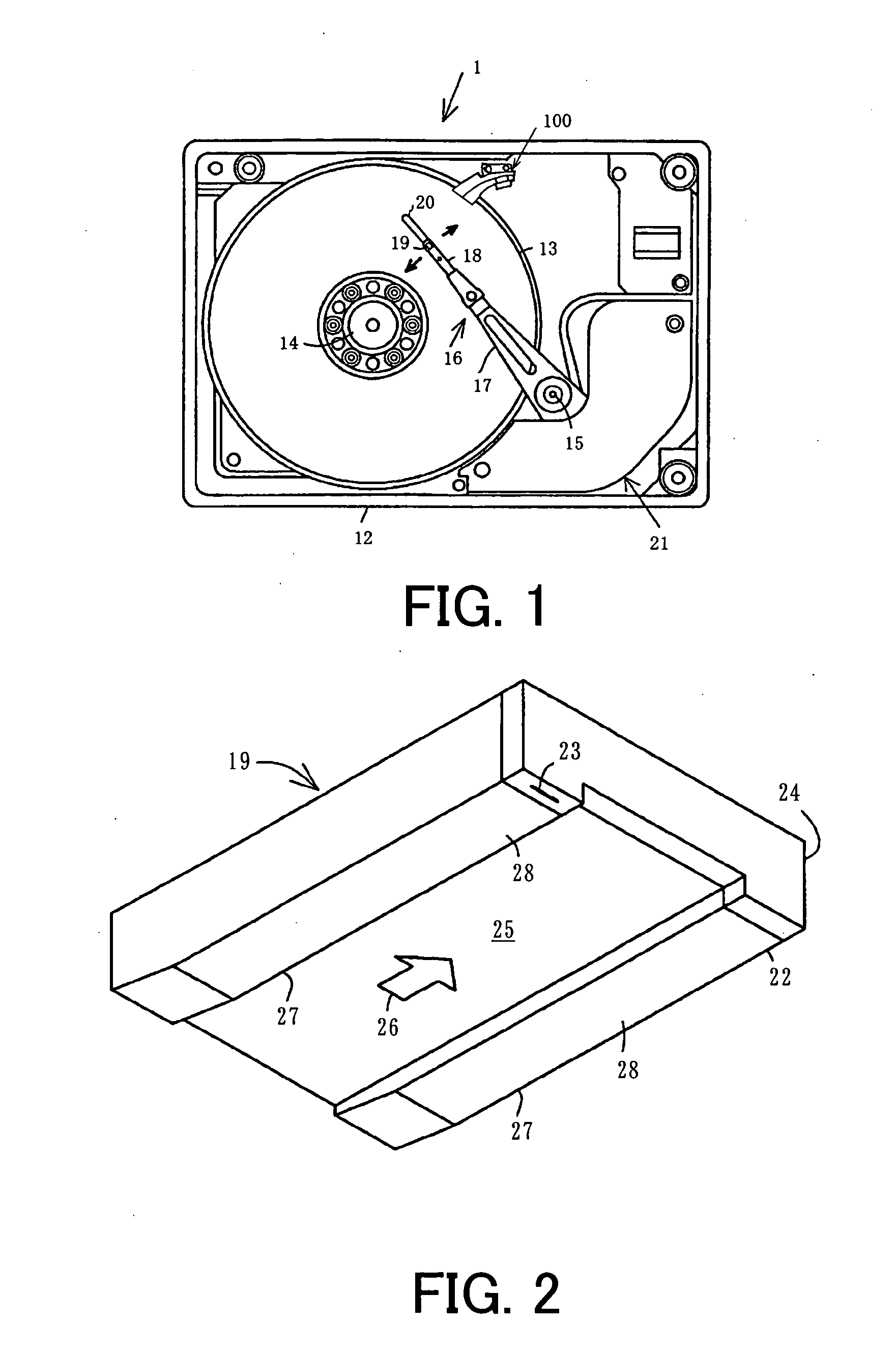
[0031] A description will be given of a HDD 1 according to one embodiment of the present invention with reference to the accompanying drawings. The HDD 1 includes, as shown in FIG. 1, one or more magnetic discs 13 as a recording medium, a spindle motor 14, a magnetic head part, and a ramp loading unit 100 in a housing 12. Here, FIG. 1 is a schematic plane view of the HDD 1's internal structure. The number of magnetic discs 13 is illustratively one in this embodiment.

[0032] The housing 12 is made, for example, of aluminum die casting or stainless steel, and has a rectangular parallelepiped shape to which a cover (not shown) for sealing the internal space is coupled. Each magnetic disc 13 in this embodiment has a high recording density, such as 100 Gb / in2 or higher, and is mounted on a spindle of the spindle motor 14.

[0033] The spindle motor 14 rotates the magnetic disc 13 at a high speed, such as 10,000 rpm, and includes a brushless DC motor (not shown) and a spindle as its rotor p...


PUM


Abstract

A ramp loading unit includes a holding part that holds, outside a recording medium, a lift tab connected to a suspension that supports a head used to record information in or reproduce the information from the recording medium, and a sliding part to which the lift tab elastically contacts in loading the head onto the recording medium and in unloading the head from the recording medium, wherein the sliding part includes an inclined part that projects at least partially above the recording medium, inclines relative to a surface of the recording medium, and partially changes an inclination angle of the inclined part.

Description

[0001] This application claims the right of foreign priority under 35 U.S.C. §119 based on Japanese Patent Application No. 2005-160078 filed on May 31, 2005, which is hereby incorporated by reference herein in its entirety as if fully set forth herein. BACKGROUND OF THE INVENTION [0002] The present relates generally to a ramp loading unit that holds a head outside a recording medium, and a drive having the ramp loading unit. The inventive drive is suitable, for example, for a hard disc drive (“HDD”). [0003] Available electronic information contents have explosively increased with the recent rapid technology developments, as in the Internet. Thus, larger-capacity magnetic storages, typified by HDDs, have been increasingly demanded to store such a large amount of information. [0004] A slider mounted with a head floats above a disc for recording and reproducing in the HDD. As a relationship between the slider and the disc at the time of activation and halt of the disc, referred to as a...

Claims


Application Information

Patent Timeline
IPC IPC(8): G11B5/54
CPCG11B5/54G11B21/22
Inventor OHWE, TAKESHI
Owner KK TOSHIBA
Learn More