Receiving apparatus and transmitting apparatus

Inactive Publication Date: 2006-11-30
SHARP KK
View PDF6 Cites 30 Cited by
  • Summary
  • Abstract
  • Description
  • Claims
  • Application Information

AI Technical Summary

Benefits of technology

[0031] The present invention has been made in view of the foregoing problems. It is an object of the present invention to provide a receiving apparatus, a transmitting apparatus, and the like, each of which makes it possible to (i) comm

Problems solved by technology

Further, although a communication service such as a TV telephone service has not been so common via the conventional telephone network because of quality and cost restrictions, such a communication service shows signs of becoming widespread.
Therefore, a user is not allowed to freely set the IP address.
Therefore, the IP address is not appropriate as an identifier for specifying the user or the terminal each making a call.
However, there are some problems with a telephone number used in either (i) the aforementioned IP telephone network or (ii) the conventional telephone network using telephone exchanging (switching) devices.
This makes it impossible to make a call to the user by using the previous telephone numbe

Method used


Image

  • Receiving apparatus and transmitting apparatus
  • Receiving apparatus and transmitting apparatus
  • Receiving apparatus and transmitting apparatus

Examples


Example

Embodiment 1

[0114] The present embodiment uses a plurality of identifiers (a known identifier, a hidden identifier, a terminal fingerprint, a certificate identifier, and an address identifier). Each of the identifiers will be explained first.

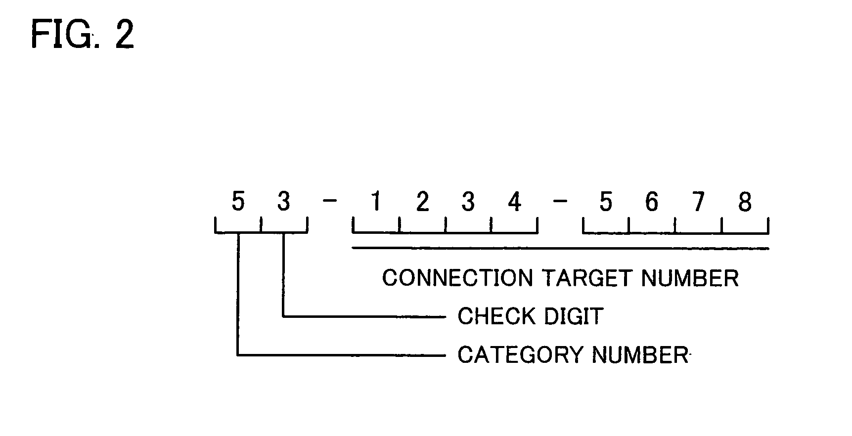
[0115] The known identifier is an identifier which corresponds to a telephone number used in the conventional telephone system, and is used in connecting a communication terminal to another communication terminal to which no connection has previously been made. For user's convenience, the known identifier may be any type of identifier as long as no problem occurs. However, in the present embodiment, a ten-digit number is used as the known identifier as shown in FIG. 2. Hyphens inserted between digits may be omitted. In the following, the digits of the known identifier are respectively referred to as a first digit, a second digit, and so on, in the order from the left.

[0116] The first digit is a category number indicating a purpose of use of t...

Example

Embodiment 2

[0209] According to the arrangement described above in Embodiment 1, one of the communication terminals notifies its hidden identifier to the other communication terminal to which the communication terminal has once been connected, so that the other communication terminal can make a connection to the communication terminal even when the communication terminal has changed its known identifier later.

[0210] However, according to the arrangement of Embodiment 1, the hidden identifier of the communication terminal is notified to the other communication terminal at the moment that the connection is made. Therefore, the unchangeable hidden identifier is sent to an unwanted person in some cases. It is possible to set up the call rejection with respect to unwanted people. However, such a setting is not reasonable.

[0211] Such an unwanted person makes connection to the user when, e.g., the known identifier is incorrectly inputted. Since the known identifier used in the present i...

Example

Embodiment 3

[0235] Basically, the present invention assumes that: the communication terminals are properly manufactured; and no improper operations are carried out. However, there may be a user who improperly alters his / her own communication terminal so as to leak, to others, a hidden identifier received by the improperly altered communication terminal. Accordingly, the present embodiment introduces a mechanism for checking which communication terminal has leaked the hidden identifier.

[0236]FIG. 22 is a diagram showing communication carried out in cases where such a checking mechanism is introduced. This is similar to the case of Embodiment 2 shown in FIG. 18. However, when communication is carried out for the first time by using a known identifier, Terminal A sends a calling message to which a certificate identifier (cer-b) is added, and Terminal B sends a connection permission response to which a certificate identifier (cer-a is added. The certificate identifier (cer-b) is gener...


PUM


Abstract

A communication terminal of the present invention includes: (i) judgment section for whether or not a hidden identifier hidden from the user and assigned fixedly and uniquely to each communication terminal or the like is included in response data transmitted from another communication apparatus in reply to transmission of connection request data including data requesting connection with the communication apparatus; and (ii) response data generating section for generating, in later calls in cases where the hidden identifier is judged to be included in the response data, reply data including (i) the hidden identifier assigned to the communication terminal and (ii) the hidden identifier received from the communication terminal.

Description

[0001] This Nonprovisional application claims priority under 35 U.S.C. § 119(a) on Patent Application No. 152909 / 2005 filed in Japan on May 25, 2005 and Patent Application No. 124489 / 2006 filed in Japan on Apr. 17, 2006, the entire contents of which are hereby incorporated by reference. FIELD OF THE INVENTION [0002] The present invention relates to a technical field of communications. Particularly, the present invention relates to an apparatus, a system, a method, and a program, whereby a call to be made between communication apparatuses via a packet-switched network is controlled by using an identifier such as a telephone number. BACKGROUND OF THE INVENTION [0003] In recent years, as accompanied with the widespread use of an always-connected Internet network, a communication service similar to a communication service using a conventional telephone network has begun to be provided via the Internet network. Further, although a communication service such as a TV telephone service has ...

Claims


Application Information

Patent Timeline
IPC IPC(8): H04L12/66H04L12/56H04L12/70H04M1/2745H04M3/42
CPCH04L29/1216H04L61/106H04L61/157H04M1/663H04M1/2745H04M1/275H04M1/57H04M1/2535H04L61/4557H04M7/006H04L65/1101
Inventor TAKAHASHI, MASAFUMIIWAI, TOSHIYUKI
Owner SHARP KK
Why Eureka
Try Eureka