

Blower and impeller structure thereof
- Summary
- Abstract
- Description
- Claims
- Application Information
AI Technical Summary
Benefits of technology
Problems solved by technology
Method used
Image

Examples
Embodiment Construction
[0016] The present invention will be apparent from the following detailed description, which proceeds with reference to the accompanying drawings, wherein the same references relate to the same elements.
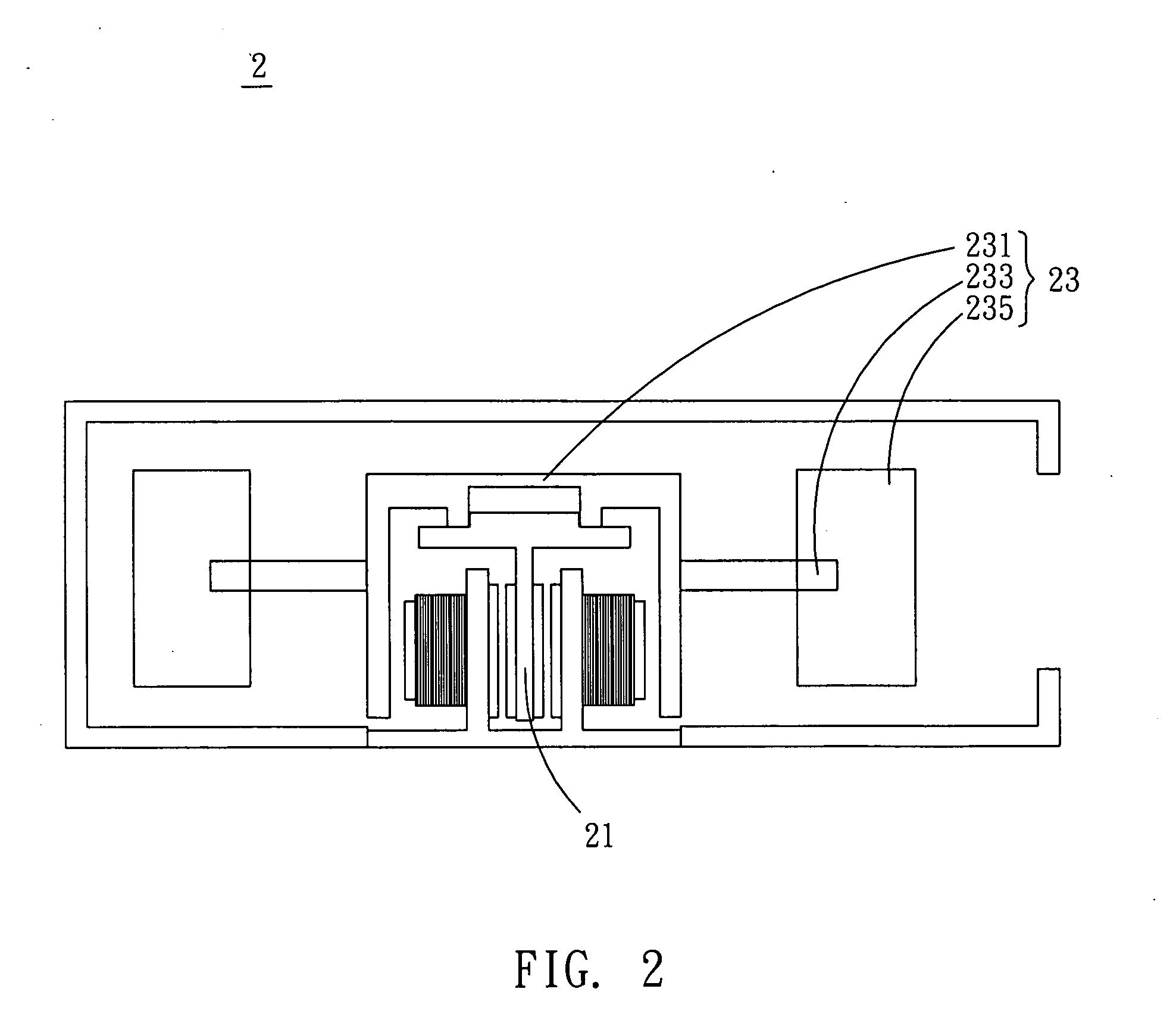
[0017] With reference to FIG. 2, a fan 2 according to a preferred embodiment of the invention comprises a driving device 21 and an impeller structure 23. The driving device 21 drives the impeller structure 23, so that an air flow is induced by the rotation of the impeller structure 23. In the embodiment, the fan 2 is a centrifugal fan or a blower, and the driving device 21 is a motor.
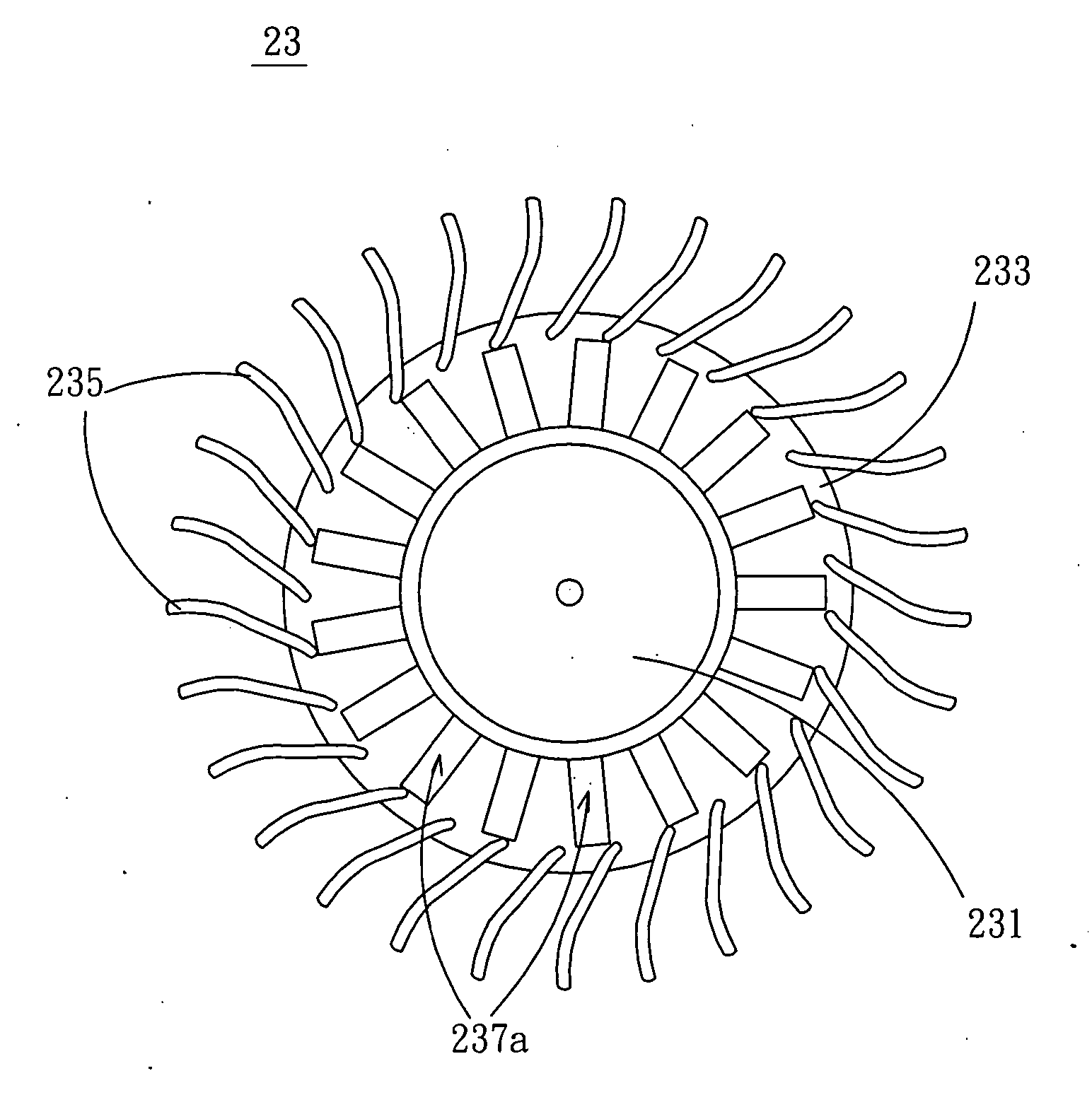
[0018] Please refer to FIGS. 3A to 3E for illustrating the detailed structure of the impeller structure 23. As shown in FIGS. 3A to 3C, the impeller structure 23 includes a hub 231, a connecting part 233, and a plurality of blades 235. In this embodiment, the connecting part 233 is disposed around the hub and connects to the hub 231. The blades 235 are disposed at the periphery of the connecting part 2...
PUM
 Abstract
Description
Claims
Application Information