
Plug and cord connector set with integrated circuitry

a technology of integrated circuits and plugs, which is applied in the direction of lighting and heating apparatus, coupling device connections, lighting support devices, etc., can solve the problems of not being able to accommodate control circuits, reducing reliability, and reducing reliability, so as to maximize led luminous intensity and minimize electricity consumption.

Active Publication Date: 2006-11-30
FIBER OPTIC DESIGNS
View PDF4 Cites 77 Cited by
  • Summary
  • Abstract
  • Description
  • Claims
  • Application Information

AI Technical Summary

Benefits of technology

[0008] It is another object of this invention to provide a standard, household plug and / or plug and cord connector pair to be used in the manufacture of decorative lighting products, particularly LED-based decorative lighting products that has integrated circuitry capable of reducing LED current.
[0011] It is another object of this invention to provide a standard, household plug and / or plug and cord connector pair to be used in the manufacture of decorative lighting products, particularly LED-based decorative lighting products that eliminates the need for additional conductor wires in a rectified light string with multiple series connections.
[0012] It is another object of this invention to provide a standard, household plug and / or plug and cord connector pair to be used in the manufacture of decorative lighting products, particularly LED-based lighting products that minimizes electricity consumption while maximizing LED luminous intensity.

Problems solved by technology

They are not designed to accommodate control circuits such as rectification, current reduction, current limiting, voltage reduction, blinking or flashing circuitry.
These circuits are added afterwards and are typically housed somewhere between the plug and cord connector, adding cost, reducing reliability, complicating the manufacturing process, and detracting from the appearance of the light string.
Moreover, the circuitry described in the prior art decreases LED life expectancy, maximizes electrical power consumption and increases the number of wires required in the manufacture of the decorative light string as series connections are added.

Method used


Image

  • Plug and cord connector set with integrated circuitry
  • Plug and cord connector set with integrated circuitry
  • Plug and cord connector set with integrated circuitry

Examples


Embodiment Construction

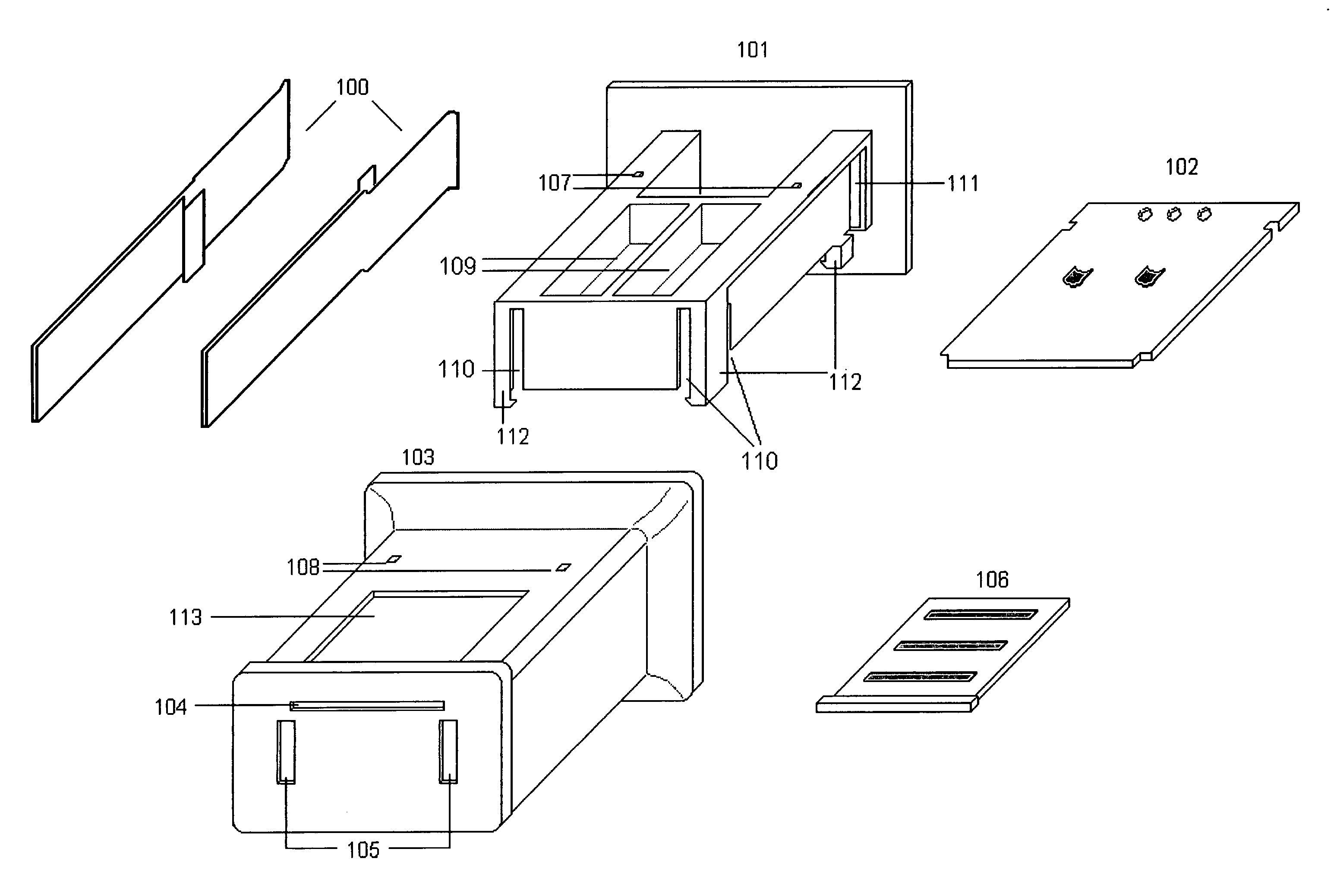
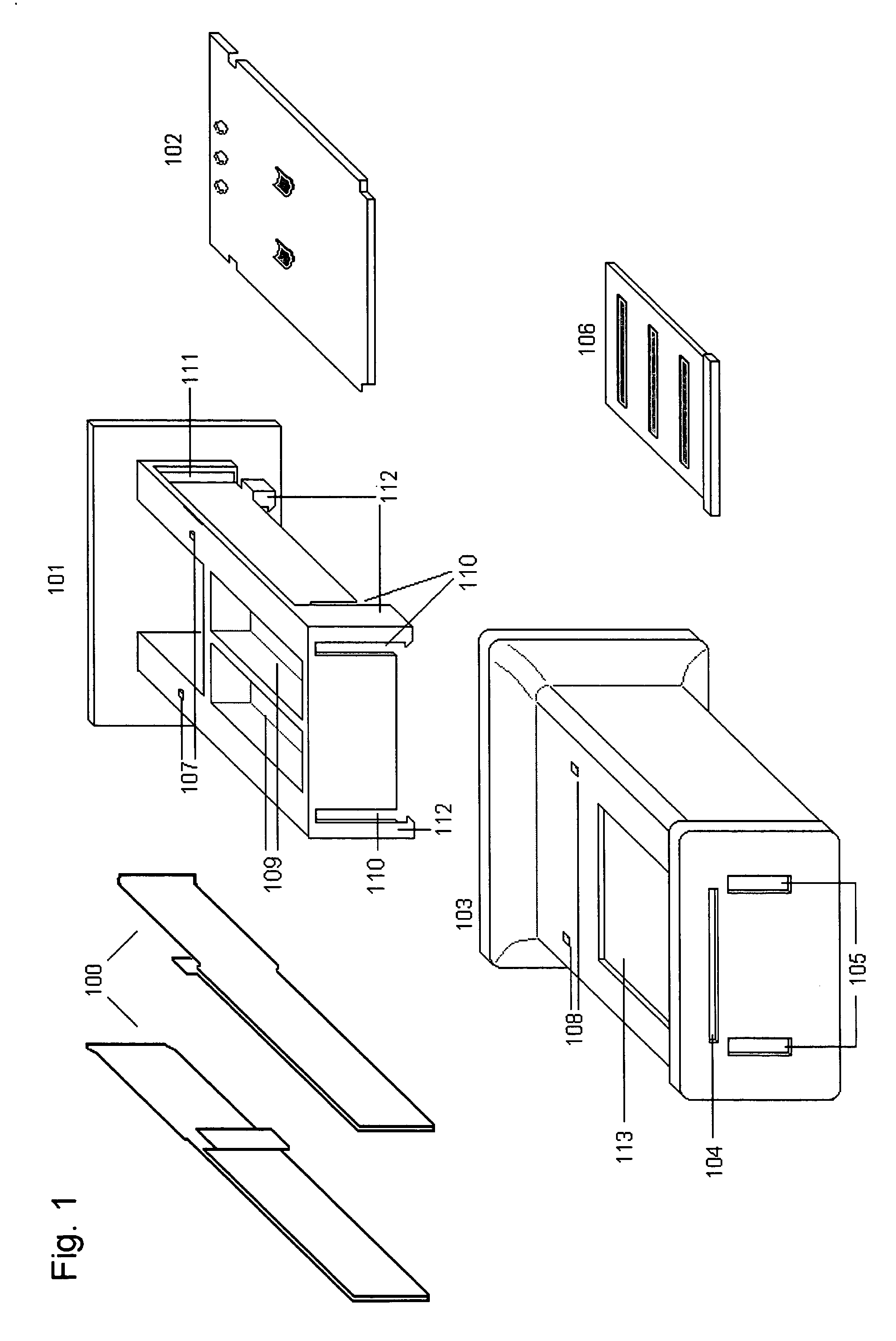
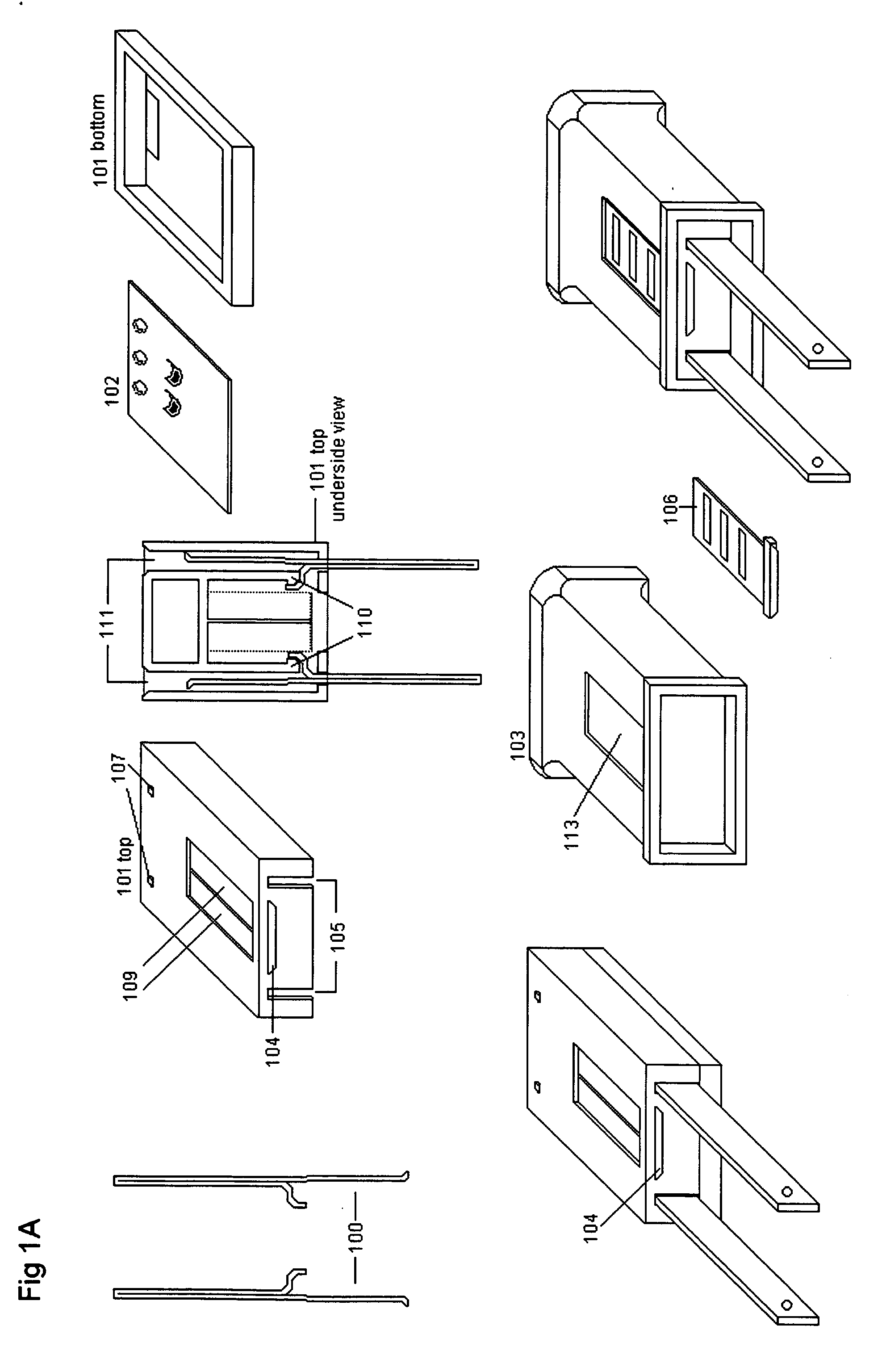
[0030] As shown in FIG. 1, the plug portion of the invention includes a pair of conductor blades (100), inner component housing (101) printed circuit board (102), protective outer shell (103) and sliding fuse cover (106).

[0031] Conductor blades (100) interface with a common household AC outlet as well as provide inbound AC electricity to the overload protection (safety fuses) and subsequent plugs connected in a “stacked” method. Conductor blades (100) are typically manufactured of copper or copper alloy. Conductor blades (100) secure symmetrically to inner component housing (101) via slots (110). In addition, conductor blades (100) can be the polarized (different blade width) or non-polarized (equal blade width) type.

[0032] Inner component housing (101) would typically be manufactured of impact resistant plastic with a high resistance to flammability and ultraviolet radiation and includes fuse compartments and separators (109), locking tabs (107), slots (111), and circuit board ta...


PUM


Abstract

A plug and / or a plug and cord connector set that is easily mass produced and includes integrated circuitry for use with decorative lighting products such as Christmas lights and rope lights. The integrated circuitry included in the plug and / or plug and cord connector combination can serve to reduce or limit current, provide full-wave AC to DC rectification, provide overload protection, reduce voltage, protect against voltage spikes, add blinking or flashing functions, or any combination thereof. An optional intermediate circuit is included for the manufacture of light strings employing multiple series connections.

Description

[0001] This application is a U.S. Non Provisional Patent Application which claims the benefit of U.S. Provisional Patent Application No. 60 / 684,561 filed May 26, 2005 and is hereby incorporated by reference in it's entirety.BACKGROUND OF THE INVENTION [0002] 1. Field of Invention [0003] The present invention relates to an improved plug, and / or plug and cord connector combination commonly used in the manufacture of decorative lighting products such as Christmas lights and rope lights. Although useful in the manufacture of incandescent based decorative lighting, the present invention is designed primarily for use with holiday and decorative lighting using LEDs (light emitting diodes) as an illumination source. An optional intermediate or junction circuit is included for the manufacture of light string employing multiple series connections. [0004] 2. Description of Related Art [0005] Plugs and cord connectors that are known in the art for use in the manufacture of decorative lighting p...

Claims


Application Information

Patent Timeline
Patent Type & Authority Applications(United States)
IPC IPC(8): H01R29/00
CPCF21S4/007H01R13/6658H01R13/6666F21Y2101/02H01R24/66H01R29/00H01R2103/00H01R13/6675F21S4/26F21Y2115/10
Inventor ALLEN, DAVID
Owner FIBER OPTIC DESIGNS
Learn More