Machine Tool

Active Publication Date: 2006-11-30
DMG MORI SEIKI CO LTD
View PDF19 Cites 105 Cited by
  • Summary
  • Abstract
  • Description
  • Claims
  • Application Information

AI Technical Summary

Benefits of technology

[0015] The present invention is directed to solving these problems, and an object of the invention is to provide

Problems solved by technology

As a result, the Y-axis cover requires frequent maintenance, or requires using a complicated and costly construction.
Another problem with the conventional technology is that the heavy saddle i

Method used


Image

  • Machine Tool
  • Machine Tool
  • Machine Tool

Examples


Embodiment Construction

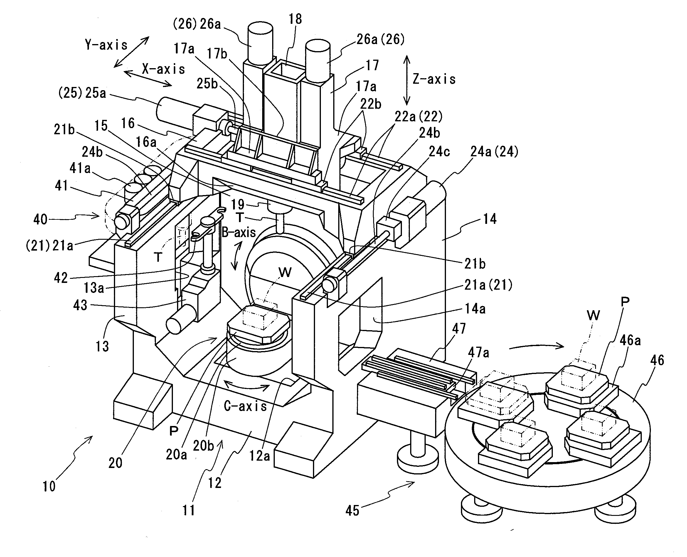
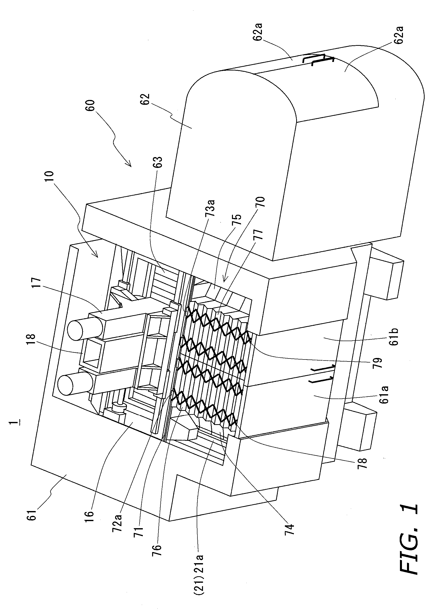
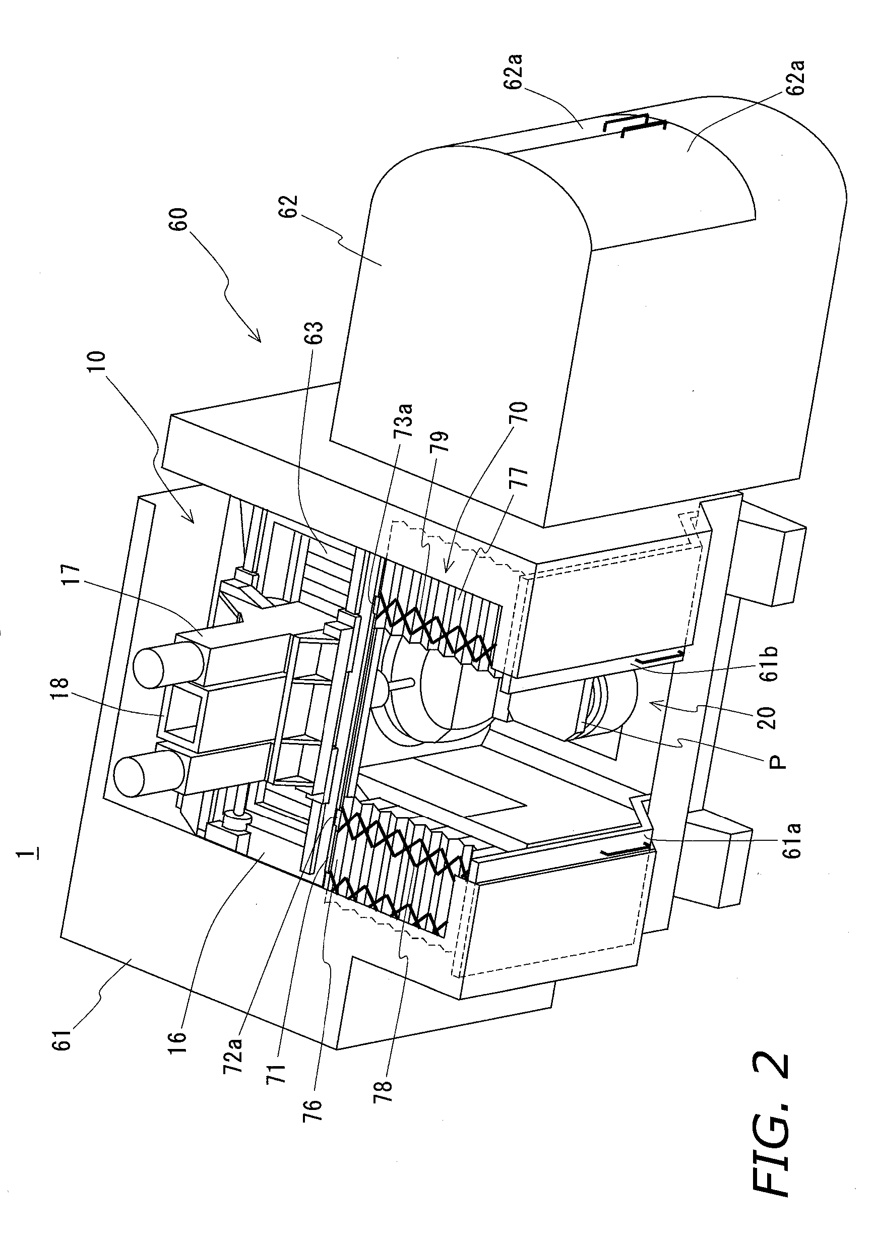
[0050] A preferred embodiment of the invention is described below with reference to the accompanying figures wherein FIG. 1 and FIG. 2 are oblique schematic views of a machine tool according to a preferred embodiment of the invention, and FIG. 3 and FIG. 4 are oblique schematic views showing the machine tool, a tool changing device, and a pallet changing device according to this preferred embodiment of the invention. FIG. 5 is a front view showing a part of a machine tool according to this preferred embodiment of the invention, and FIG. 6 is a section view through line A-A in FIG. 5. FIG. 7 and FIG. 8 are plan views showing a part of the top cover in this preferred embodiment of the invention, FIG. 9 is a section view through line B-B in FIG. 7, and FIG. 10 is a section view through line C-C in FIG. 8.

[0051] As shown in FIG. 1 to FIG. 6, a machine tool 1 according to this embodiment of the invention has a machine tool unit 10 of a type known as a vertical machining center, a tool c...


PUM

PropertyMeasurementUnit
Angleaaaaaaaaaa
Angleaaaaaaaaaa

Abstract

Machine tool simplifying maintenance, reducing manufacturing costs, and enabling high precision machining. The machine tool is equipped with: a bed furnished with a rectangular base, right and left sidewalls provided standing either side of the base, and a rear sidewall provided standing along the back of the base; a table disposed in the space surrounded by the three sidewalls; a first saddle shaped in the form of a rectangular frame shape, provided free to shift back and forth supported on the tops of the left and right sidewalls; a second saddle penetrated by a perpendicular through-hole and arranged free to shift sideways inside the first saddle frame; and a spindle head arranged free to shift perpendicularly inside the through-hole in the second saddle; and a main spindle arranged over the table and supported by the spindle head free to rotate centered on its axis.

Description

BACKGROUND OF THE INVENTION [0001] 1. Technical Field [0002] The present invention relates to machine tools furnished with: a bed; a table on which a workpiece is carried and which is disposed on the bed; a main spindle for retaining a tool, and provided, with its axis disposed perpendicularly, to rotate freely centered on the axis; and a feed mechanism for shifting the table and the main spindle relatively to each other along three orthogonal axes. [0003] 2. Description of the Related Art [0004] Such machine tools known to date include the example disclosed in Japanese Unexamined Patent App. Pub. 2001-87964. This machine tool primarily is made up of: a bed; a column arranged on the bed; a saddle that is supported on the front of the column and is shiftable horizontally (along the X-axis); a spindle head that is supported on the saddle and is shiftable vertically (along the Z-axis); a main spindle for retaining a tool and being supported by the spindle head so that the axis of the m...

Claims


Application Information

Patent Timeline
IPC IPC(8): B23Q3/157B23Q11/08B23Q11/00B23C1/14
CPCB23Q1/012Y10T409/309576B23Q1/626B23Q7/1431B23Q11/005Y10T483/16Y10T29/5196Y10T409/308288Y10T409/307728Y10T409/30392Y10T409/304032Y10T409/305824Y10T29/5114Y10T409/305656Y10T483/115Y10T29/5124Y10T409/304088Y10T483/176B23Q1/5406
Inventor TAKAYAMA, NAOSHIWATANABE, MICHIOKIMURA, NOBUYUKIHIRAMOTO, KAZUYUKIAKAI, TAKAYUKI
Owner DMG MORI SEIKI CO LTD
Why Eureka
Try Eureka