Calibrated surgical probe

a surgical probe and probe body technology, applied in the field of surgical instruments, can solve the problems of manual adjustment of the port opening, add time and expense to the process, and ophthalmic surgeons do not have simple tools available to measure feature size or fluid depth,

Inactive Publication Date: 2006-11-30
ALCON INC
View PDF16 Cites 53 Cited by
  • Summary
  • Abstract
  • Description
  • Claims
  • Application Information

AI Technical Summary

Benefits of technology

[0020]FIG. 6 shows a simplified block diagram of certain portions of the electronic and pneumatic

Problems solved by technology

Some negative aspects exists with regard to this prior art alignment method.
After assembly, the only indication of accurate alignment is probe performance during a cut test, which adds time and expense to the process.
A further disadvantage of prior art vitrectomy probes is illustrated in that typically ophthalmic surgeons do not have simple tools available to measure feature size or fluid depth within the eye during a surgical procedure.
Manually adjusting the port opening, however, can

Method used


Image

  • Calibrated surgical probe
  • Calibrated surgical probe
  • Calibrated surgical probe

Examples


Embodiment Construction

[0021] Preferred embodiments of the present invention are illustrated in the FIGUREs, like numerals being used to refer to like and corresponding parts of the various drawings.

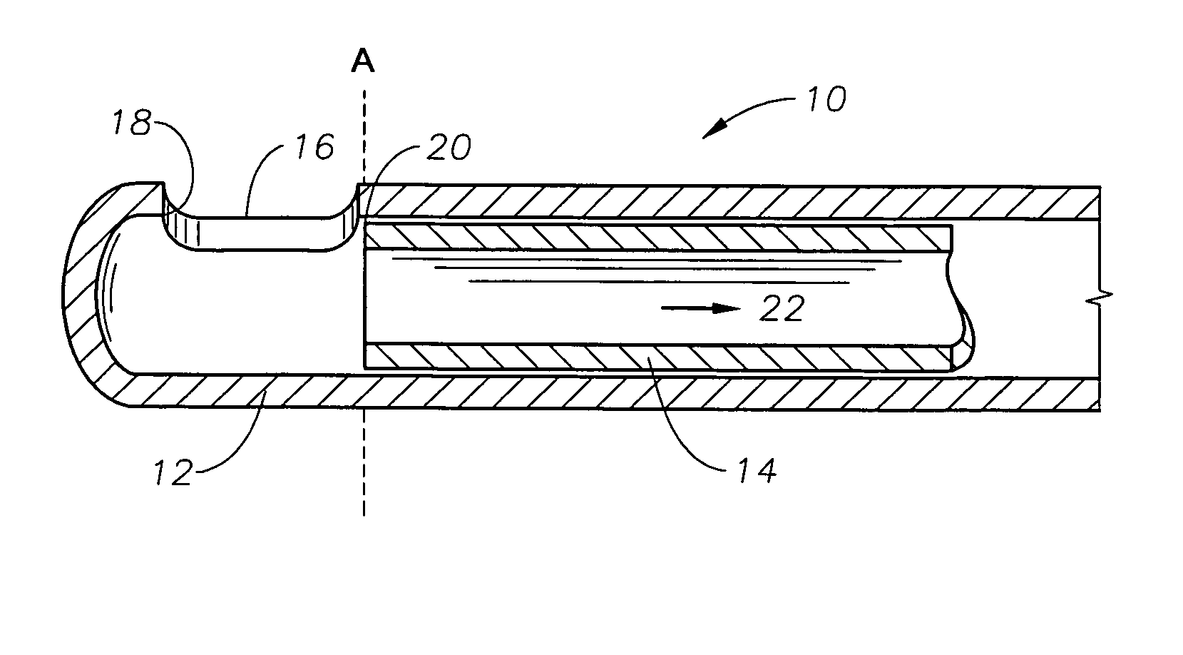
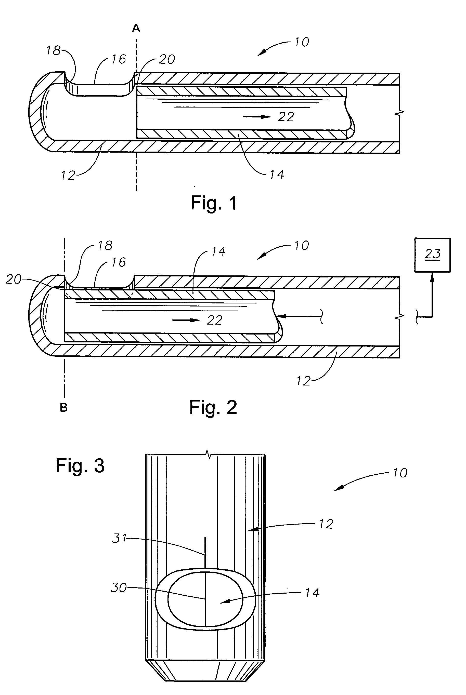
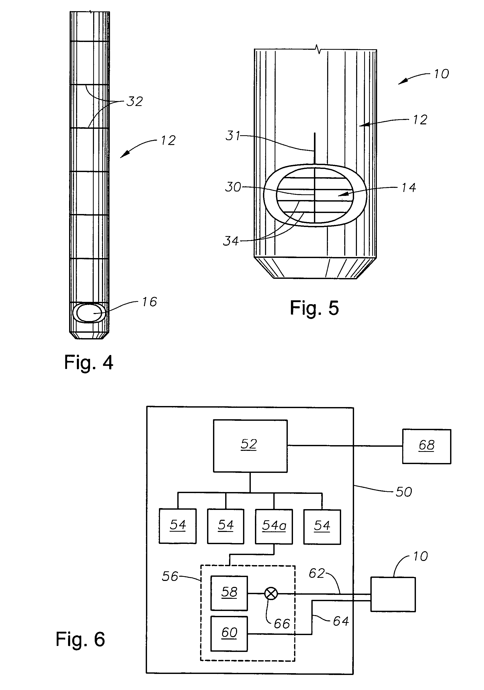
[0022] The various embodiments of the present invention provide for a calibrated surgical probe for use in surgical procedures, such as in vitro-retinal / posterior segment surgery. Embodiments of this invention can comprise a vitrectomy probe tip with alignment marks on an internal cutting member and / or an external cutting member, as shown in FIG. 3. Other embodiments of this invention can comprise a vitrectomy probe tip having measurement gauge marks on the outer cutting member, as shown in FIG. 4. Further embodiments can include radial marks on the inner cutting member near the cutting edge to indicate the port opening size, as shown in FIG. 5. Embodiments of the calibrated surgical probe tip of this invention can be configured for use in the general field of ophthalmic surgery. However, it is contemplated a...


PUM


Abstract

A microsurgical probe tip and method of using same are disclosed. One embodiment of the microsurgical probe tip comprises: an outer cutting member, comprising a first tube having a wall, a closed end and a port formed in the wall near the closed end; an inner cutting member, comprising a second tube coaxial with and operable to move in a reciprocating motion within the first tube and having a first end operable to be coupled to a driving mechanism and a second end with a cutting edge for cutting tissue; a first alignment mark on the outer cutting member at a first predetermined position adjacent to the port; and a second alignment mark on the inner cutting member at a second predetermined position adjacent to the cutting edge of the inner cutting member, wherein the second alignment mark is visible through the port and operable to be aligned with the first alignment mark such that when the first and second alignment marks are aligned, a preferred relative positioning between the inner and outer cutting members is achieved. The microsurgical probe tip can further comprise one or more radial alignment marks on the inner cutting member, wherein the radial alignment marks are parallel to one another at fixed intervals from one another and positioned so that one or more of the radial alignment marks are visible through the port so as to indicate the relative lateral positioning between the inner cutting member and the outer cutting member. The radial alignment marks can be made by a method, or combination of methods, such as laser cutting, inkjet printing, and mechanical scribing. The driving mechanism can be a pneumatic driving mechanism, an electro-mechanical driving mechanism, and/or a magnetic driving mechanism. The microsurgical probe tip can further comprising a plurality of gauge marks on an outer surface of the outer cutting member, wherein the gauge marks are parallel to one another at a fixed interval (e.g., 1 millimeter) from one another and positioned so that the gauge marks can be used as a measuring tool in a surgical environment

Description

CROSS-REFERENCE TO RELATED APPLICATIONS [0001] This application claims priority under 35 U.S.C. §119 to U.S. Provisional Patent Application No. 60 / 685,997, filed May 31, 2005, the entire contents of which are incorporated herein by reference.TECHNICAL FIELD OF THE INVENTION [0002] The present invention relates generally to surgical instruments and, more particularly, to surgical instruments used in ophthalmic surgery. Even more particularly, the present invention relates to instruments, such as vitrectomy probes, suitable for use in performing micro-surgical procedures in the posterior portion of the eye. BACKGROUND OF THE INVENTION [0003] Many micro-surgical procedures require precision cutting and / or removal of various body tissues. For example, certain ophthalmic procedures require the cutting and / or removal of the vitreous humor, a transparent jelly-like material that fills the posterior segment of the eye. The vitreous humor, or vitreous, is composed of numerous microscopic fib...

Claims


Application Information

Patent Timeline
IPC IPC(8): A61B17/32
CPCA61B17/32002A61F9/00763A61B2019/4857A61B2090/0811
Inventor KIRCHHEVEL, G. LAMARZALESKI, RICHARD L. IILIN, DEAN Y.ZICA, MICHAEL A.
Owner ALCON INC
Why Eureka
Try Eureka