Friction hinge with viscous damping

a technology of viscous damping and friction hinge, which is applied in the field of friction hinge with viscous damping, can solve the problems of video screen, laptop lid that slams shut, and low performance, and achieve the effect of easy and firmly attached

Inactive Publication Date: 2006-12-07
TORQMASTER INC
View PDF25 Cites 44 Cited by
  • Summary
  • Abstract
  • Description
  • Claims
  • Application Information

AI Technical Summary

Benefits of technology

[0013] The object of our invention is to provide a hinge that combines the holding characteristics of friction hinges and which also has the benefits of hydraulically damped motion control when rotating.
[0014] Another object of our invention is to provide a hinge that combines friction for positioning and viscous damping for motion control in a small size.
[0015] Yet another object of our invention is to provide the frictional and the damping characteristics in a hinge that is compact and yet is easily and firmly attached to each of the elements whose motion is to be controlled thereby.

Problems solved by technology

However, their performance is less then ideal because the static coefficient of friction between any two contacting elements is always substantially larger then the dynamic coefficient despite efforts to make the difference as small as possible.
This can result in laptop lids that slam shut and video screen in cars that swing too freely from their overhead mounts.
This can be merely annoying or it can cause damage to the video screen or to its mountings.

Method used


Image

  • Friction hinge with viscous damping
  • Friction hinge with viscous damping
  • Friction hinge with viscous damping

Examples


Embodiment Construction

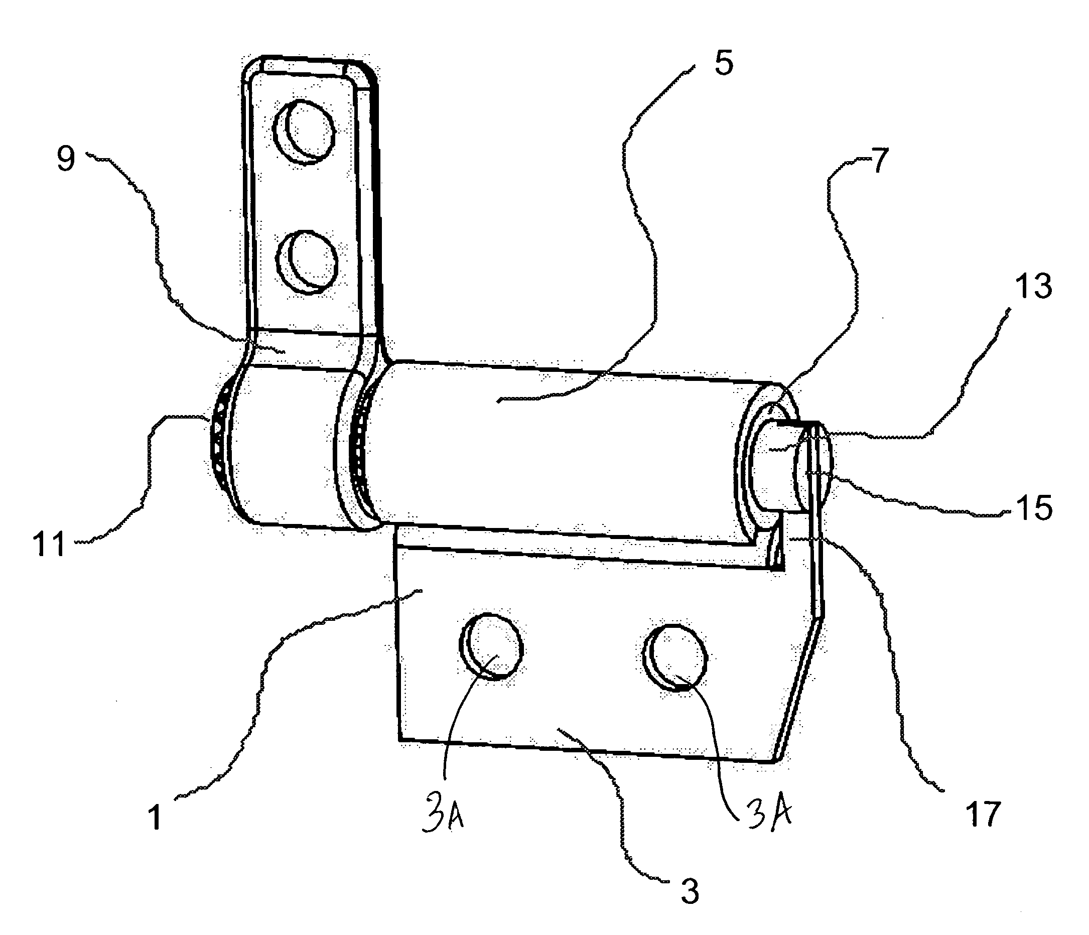
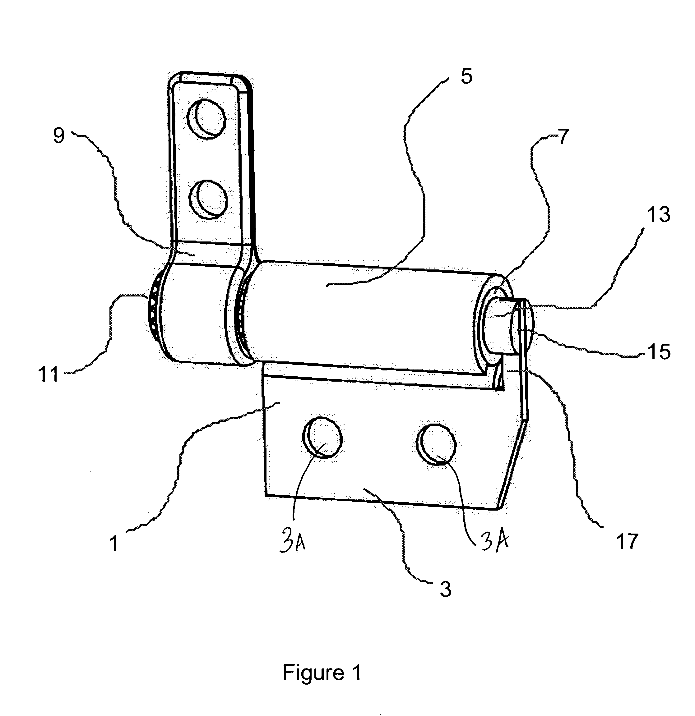
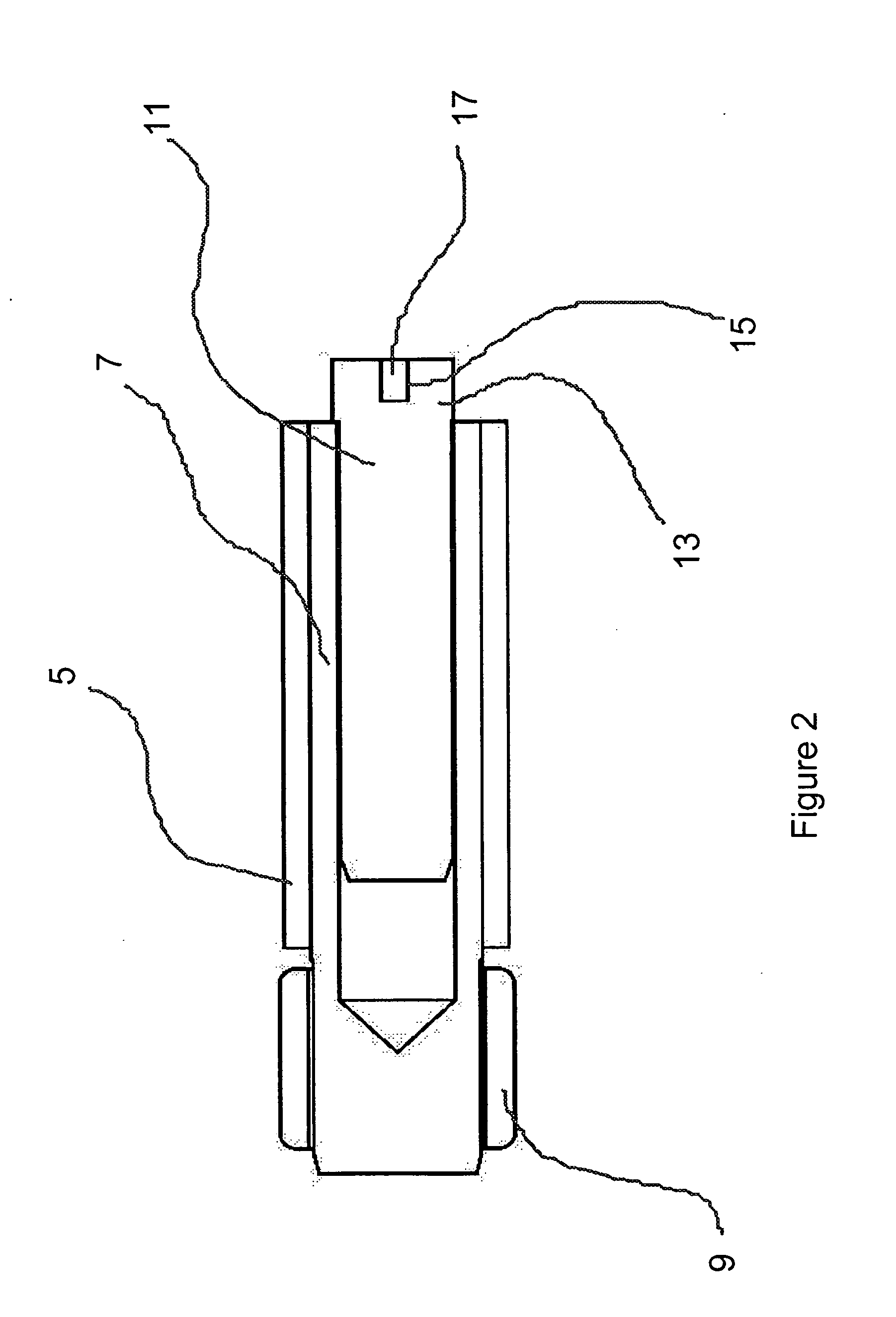
[0029] Referring now to FIGS. 1, 2, and 3, the subject hinge includes a question-mark shaped band 1 with a mounting flange 3 (visible only in FIGS. 1 and 3), a circular portion 5, a sleeve or annual element 7 and a shaft 11. The flange 3 is formed with a plurality of holes 3A for mounting to one of the components to be connected by the hinge of our invention. Though shown as flat, the flange 3 can be formed to any other convenient shape. Similarly, the number, size and shape of the mounting holes 3A can changed as needed. Moreover, instead of flange 3 other firm mounting means can be employed.

[0030] The circular portion 5 is formed to a slightly smaller size than the outside diameter of annular element 7. The difference between the respective sizes of these two components determines the frictional torque generated therebetween. In assembly, band 1 is pressed over annular element 7. Relative rotation of one of these with respect to the other will, according to the well know principl...


PUM


Abstract

A hinge assembly rotationally connecting two components includes at least a shaft coupled to one of the components and a tubular member connected to the other component and a defining an annular space around said shaft. A viscous damping fluid is disposed in said space and provides a damping force resisting relative rotation between the two components. A second tubular member is also provided that is connected to the shaft and is arranged axially around the first tubular member. In this latter configuration, static and dynamic frictional forces are generated between the tubular members that resist rotation between the components as well.

Description

RELATED APPLICATIONS [0001] The subject matter of this application is related to our commonly owned U.S. patent application Ser. No. ______ filed ______ based on U.S. Provisional application No. 60 / 687,483, file Jun. 4, 2005, entitled Friction Hinge with Angularly Dependent Torque; and U.S. Patent publication entitled Reinforcer For Wrapped Band Hinges, No. 20050028321, published Feb. 10, 2005, both incorporated herein by reference.BACKGROUND TO THE INVENTION [0002] a. Field of Invention [0003] This invention pertains to a novel hinge in which two cylindrical surfaces are separated by a space that is filled with a viscous damping fluid to generate a frictional force between the two surfaces that is proportional to the relative rotational speed of the two surfaces. Other surfaces are provided in the hinge that generate static and dynamic frictional forces controlling the movement of various hinge elements. [0004] b. Description of the Prior Art [0005] Friction hinges are now found in...

Claims


Application Information

Patent Timeline
Patent Type & Authority Applications(United States)
IPC IPC(8): E05D11/08
CPCE05D11/082E05F5/00E05Y2201/21Y10T16/54038E05Y2201/266E05Y2900/606E05Y2201/254
Inventor RUDE, EDWARD T.BROKOWSKI, WALTER
Owner TORQMASTER INC
Why Eureka
Try Eureka