Method of contructing large towers for wind turbines

a technology of wind turbines and large towers, applied in the direction of structural elements, sustainable buildings, building components, etc., can solve the problems of increasing the amount of manual work on inappropriate places, increasing the cost of materials, and increasing the requirement for transportation vehicles, so as to reduce the amount of manual work on site

Active Publication Date: 2006-12-07
VESTAS WIND SYST AS
View PDF7 Cites 70 Cited by
  • Summary
  • Abstract
  • Description
  • Claims
  • Application Information

AI Technical Summary

Benefits of technology

[0024] f) mounting tower sections on top of each other by connecting them along their opposing horizontal flanges by connecting means, e.g. bolts.
[0025] In an advantageous embodiment of the method, the rolled steel plate constituting a 360° shell is being welded together to form a cylindrical or tapered tower section, whereupon said section is cut into the number of elongated shell segments required.
[0026] In another advantageous embodiment of the method and previous to step a), a number of rolled elongated shell segments are being welded together along their abutting horizontal edges to establish larger lengths of tower shell segments.
[0027] Furthermore, the method will preferably include the flanges in step b) being welded in a position pointing towards the center of the tower. This leaves a smooth outer surface of the tower.
[0028] The vertical flanges are preferably being welded in such distance from the edge of the respective shell that a spacer bar could be sandwiched between the flanges as they are tightened together. A vertical joint visible after interconnecting two neighbour shells via a spacer bar is preferably being covered by inserting a filler material and / or a filler element.
[0029] In a preferred method according to the invention, interconnection of horizontal flanges is performed after offsetting the vertical division lines of neighbour tower sections. Also fitting out each shell with necessary ladders etc. should preferably be performed before transportation to the site, thereby reducing on-site work as much as possible.

Problems solved by technology

Increased thickness would mean higher material costs and a requirement for heavier transportation vehicles, be it trucks, trains, ships or helicopters, while diameters need to be small enough to allow for vehicle heights not exceeding typically 4.20 m in order to pass under bridges and through tunnels.
However, such solution has the disadvantage of claiming a larger amount of manual work on inappropriate places and maybe adding supporting structures to the subparts, which is the reason why this has not been considered a profitable solution.

Method used


Image

  • Method of contructing large towers for wind turbines
  • Method of contructing large towers for wind turbines
  • Method of contructing large towers for wind turbines

Examples


Embodiment Construction

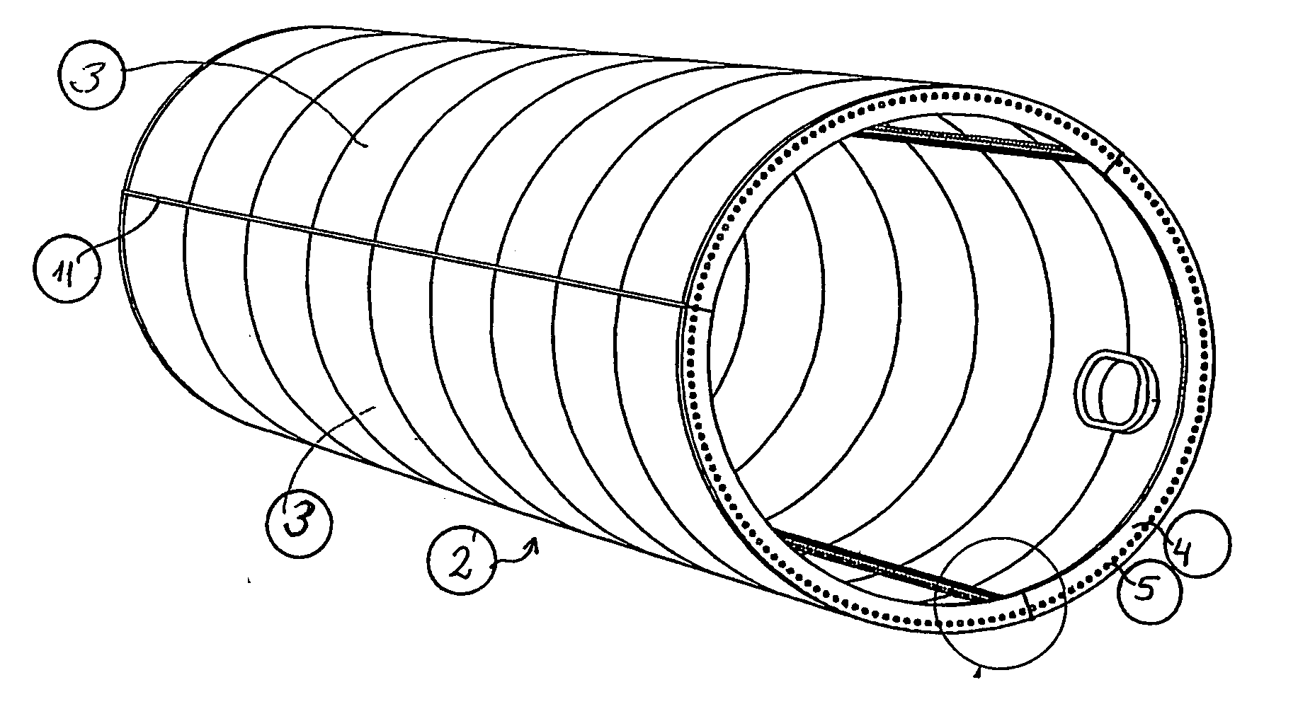
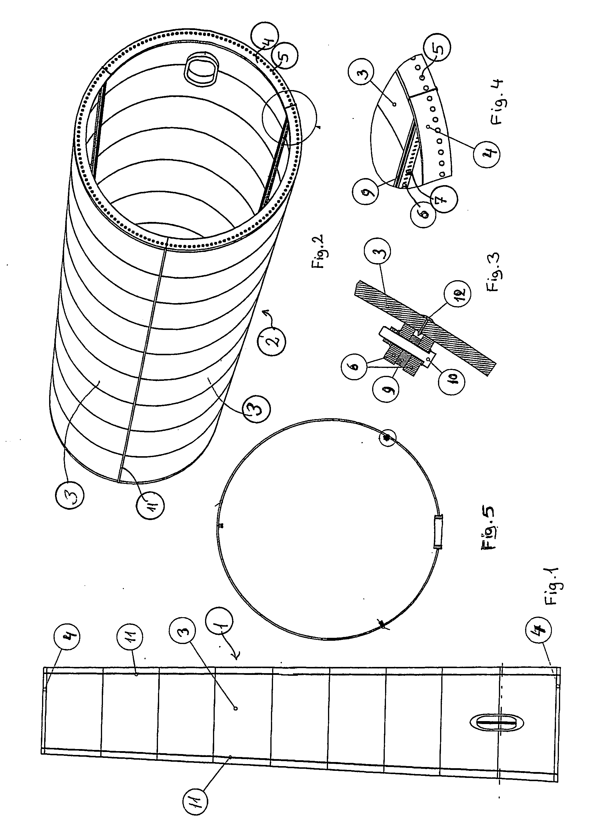
[0045] A shell segment of a windmill tower built according to the invention is shown in FIG. 1 and further details are shown in FIGS. 2-5. The tower comprises a number of shell segments I of rolled steel plates, which bolted together side-by-side make up complete circumferential tower sections 2 (see FIGS. 2 and 5), said sections being secured one on top of another by bolts (see FIGS. 3 and 4). In FIG. 2, a segment 3 shows several lengths 3 of shell welded together along abutting upper and lower edges. Each top and bottom edge of a combined length of shell segments 3 are provided with a plane flange 4 extending inwardly and carrying a large number of throughholes 5 to receive corresponding bolts for tightening sections securely together.

[0046] Plane vertical flanges 6 provided with a large number of throughholes 7 are welded in such distance from the edge of the respective shell that an elongated spacer bar 9 could be sandwiched between the vertical flanges 6, as they are tightened...


PUM


Abstract

In order to transport large size windmill towers, the invention suggests a steel tower (1) for a windmill, comprising a number of cylindrical or tapered tower sections (2), at least the wider sections (2) of which being subdivided into two or more elongated shell segments (3), which combine into a complete tower section (2) by means of vertical flanges (6) tightened together, e.g., by bolts (10), said shells being also provided with upper and lower horizontal flanges (4), respectively, to allow interconnection of tower sections (2) one on top of the other.

Description

FIELD OF THE INVENTION [0001] The invention relates to large size windmill towers of single-walled steel tower sections, each being comprised of prefabricated shell segments [0002] For many years it has been common practice to build steel tower sections separately in a workshop facility and then to move each complete section to the site, where the windmill installation is to be performed. The tower sections would typically have a cylindrical or slightly tapered shape, and each of the sections could in turn be divided along axial lines into an adequate number of shells. [0003] Due to the ever-increasing demand for larger capacity windmills and consequently larger dimensions of all parts needed to build such mills, a physical limit imposed by the infrastructure, e.g. the clearance beneath a bridge or in a tunnel, is reached. [0004] Accordingly, the idea of subdividing tower structures in order to ease the transportation thereof would be an obvious solution to suggest. PRIOR ART [0005]...

Claims


Application Information

Patent Timeline
Patent Type & Authority Applications(United States)
IPC IPC(8): E04C5/08F03D1/00F03D11/04
CPCE04H12/085F03D1/001Y02E10/728F05B2240/912Y02B10/30F03D11/04F03D13/10F03D13/20Y02E10/72
Inventor JENSEN, SORENP
Owner VESTAS WIND SYST AS
Why Eureka
Try Eureka