Practical method for improving the efficiency of cogeneration system

a cogeneration system and efficiency improvement technology, applied in mechanical equipment, machines/engines, lighting and heating apparatus, etc., can solve the problems of increasing the recirculation rate of exhaust gas, reducing the oxygen concentration at the inlet of the furnace, and reducing the heat energy lost through the stack, so as to achieve the effect of increasing the recirculation rate and generating heat energy

Inactive Publication Date: 2006-12-07
PRANDA PAVOL +1
View PDF18 Cites 21 Cited by
  • Summary
  • Abstract
  • Description
  • Claims
  • Application Information

AI Technical Summary

Benefits of technology

[0008] Embodiments of the present invention generally relate to an exhaust gas recirculation system which maintains a desired oxygen concentration for stable combustion at increased recirculation rates. In one embodiment, a method for generating heat energy is provided. The method includes the acts of mixing a first stream of exhaust gas with a stream of fresh air, thereby forming a first mixture; igniting the first mixture with a stream

Problems solved by technology

The power generation research and development community faces an important challenge in the years to come: to produce increased amounts of energy under the more and more stringent constraints of increased efficiency and reduced pollution.
Heat energy lost through the stack also decreases with an increase in recirculation rate of the exhaust gas

Method used


Image

  • Practical method for improving the efficiency of cogeneration system
  • Practical method for improving the efficiency of cogeneration system
  • Practical method for improving the efficiency of cogeneration system

Examples


examples

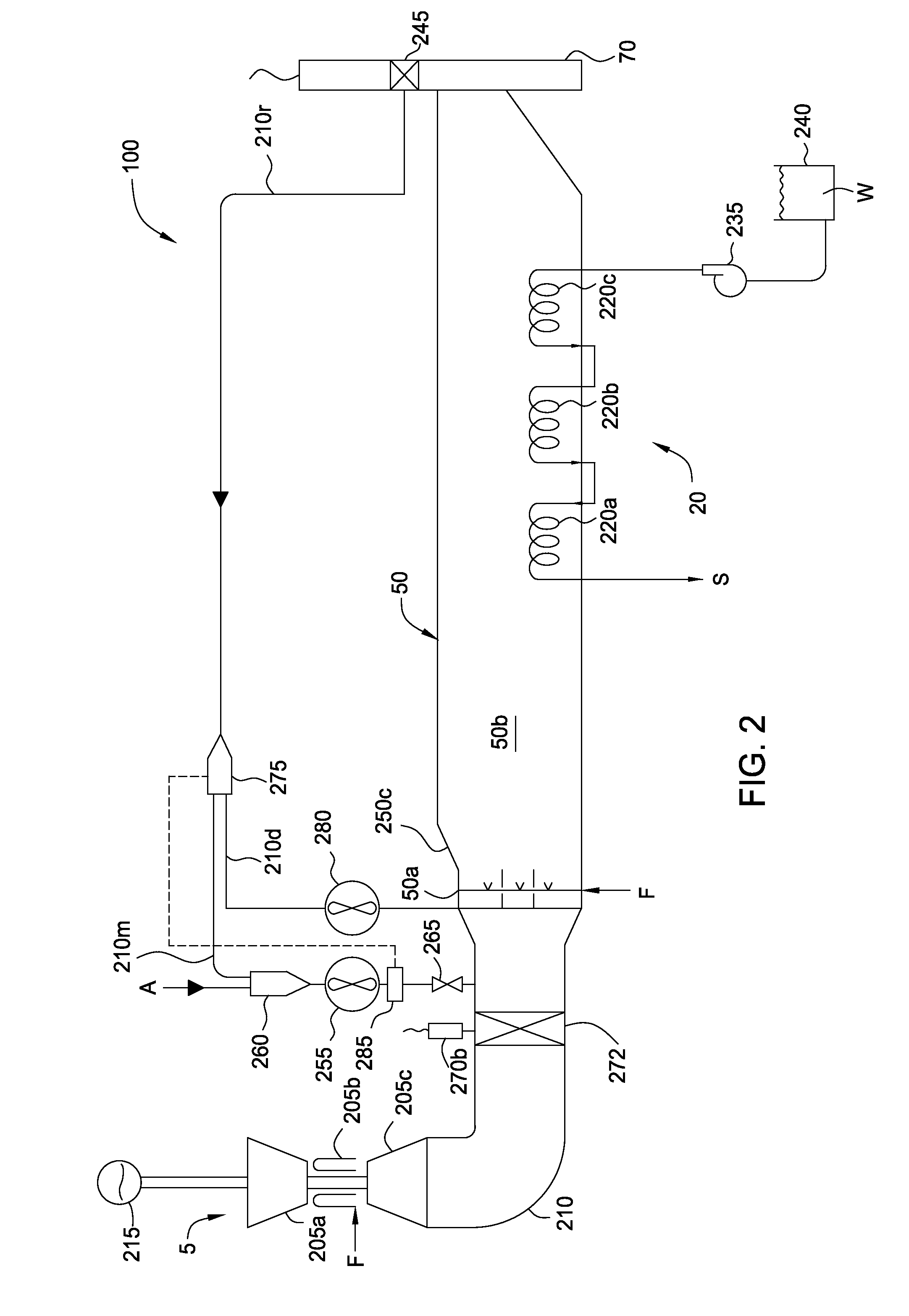
[0025] Table 1 exhibits the beneficial effect of diverting a portion of the recycled exhaust gas and injecting the diverted recycled gas (DRE) gas 25d downstream of the burner 50b. The DRE entries marked by an “X” were simulated with the cogeneration system 100 operating in fresh air mode, whereas, the entries not marked were simulated for a conventional recycled gas cogeneration system operating in fresh air mode. The recirculation rate column for the DRE entries reflect an overall rate measured at the deflection damper 245. In each of the DRE entries, the diverter controller 275c was set to maintain acceptable oxygen content to the duct burner 50a (measured in the recirculation sub-duct 210) for stable combustion of between about 18% and about 18.5%, thereby improving the global efficiency of the cogeneration system 100. Alternatively, but less preferably, the diverter controller may be set to maintain the oxygen content at about 17.5% and, least preferably, at about 17%, accordin...


PUM


Abstract

Systems and methods for exhaust gas recirculation in which a desired oxygen concentration is maintained for stable combustion at increased recirculation rates. Exhaust gas of an energy generation system is divided and reintroduced at different locations of the system.

Description

CROSS-REFERENCE TO RELATED APPLICATIONS [0001] This application claims the benefit under 35 U.S.C. § 119(e) to provisional application No. 60 / 686,295, filed Jun. 1, 2005, the entire contents of which are incorporated herein by reference.BACKGROUND [0002] The power generation research and development community faces an important challenge in the years to come: to produce increased amounts of energy under the more and more stringent constraints of increased efficiency and reduced pollution. The increasing costs associated with fuel in recent years further emphasize this mandate. [0003] Gas turbines offer significant advantages for power generation because they are compact, lightweight, reliable, and efficient. They are capable of rapid startup, follow transient loading well, and can be operated remotely or left unattended. Gas turbines have a long service life, long service intervals, and low maintenance costs. Cooling fluids are not usually required. These advantages result in the wi...

Claims


Application Information

Patent Timeline
IPC IPC(8): F02C6/04
CPCF01K23/103F22B1/1861Y02E20/14F22G5/06F22B35/002
Inventor PRANDA, PAVOLHU, TAILAI
Owner PRANDA PAVOL
Why Eureka
Try Eureka