
Beach umbrella

a beach umbrella and umbrella technology, applied in the field of beach umbrellas, can solve the problems of cumbersome and low stability, premature aging of the skin, and heavy weight of standard beach umbrellas, and achieve the effect of light weight and convenient setting up

Inactive Publication Date: 2006-12-07
TANNER ROBERT +1
View PDF25 Cites 32 Cited by
  • Summary
  • Abstract
  • Description
  • Claims
  • Application Information

AI Technical Summary

Benefits of technology

[0015] The present invention relates to a beach umbrella that is stable, light weight, and easy to set up.
[0017] It is another object of the invention to provide a beach umbrella wherein the anchoring means is integral to the lower half of the shaft, thereby enhancing stability and reducing weight.
[0019] It is a further object of the invention to provide a beach umbrella having enhanced wind stability through the use of slits or vents in the umbrella canopy.
[0020] It is a further object of the invention to provide a beach umbrella having a canopy with stays that provide a backbone structure, such that the canopy can be flipped inside and out in windy weather and then be easily flipped back into shape. According to a preferred embodiment, the stays are made of fiberglass, wood or pliable plastic.
[0026] It is another object of the invention to provide a beach umbrella and / or a beach umbrella canopy wherein the pole and / or shaft is a strong and light-weight material that is resistant to corrosion such as aluminum, titanium or stainless steel.
[0028] The general purpose of the present invention, which will be described subsequently in greater detail, is to provide a new beach umbrella that has many of the advantages set forth above and many novel features that result in a new beach umbrella that is not anticipated, rendered obvious, suggested, or even implied by any of the prior art beach umbrellas, either alone or in any combination thereof. In these respects, the beach umbrella of the present invention substantially departs from the conventional concepts and designs of the prior art, and in so doing provides an apparatus primarily developed for the purpose of providing a beach umbrella that is stable, light weight, and easy to set up.

Problems solved by technology

Further, sun exposure has been shown to cause premature aging of the skin.
However, standard beach umbrellas are heavy, and cumbersome with low stability.

Method used


Image

  • Beach umbrella
  • Beach umbrella
  • Beach umbrella

Examples


Embodiment Construction

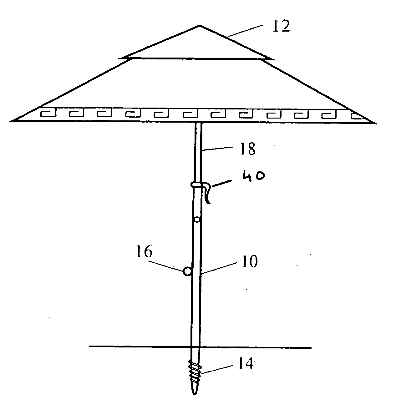
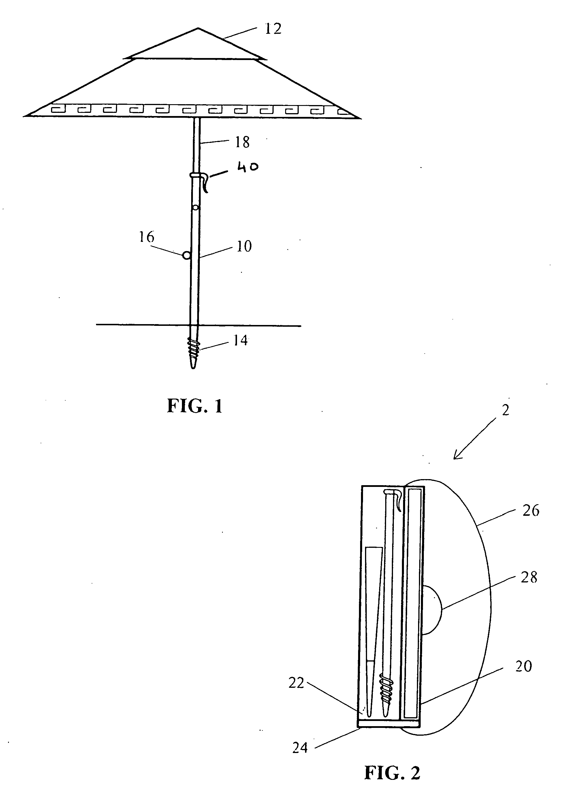
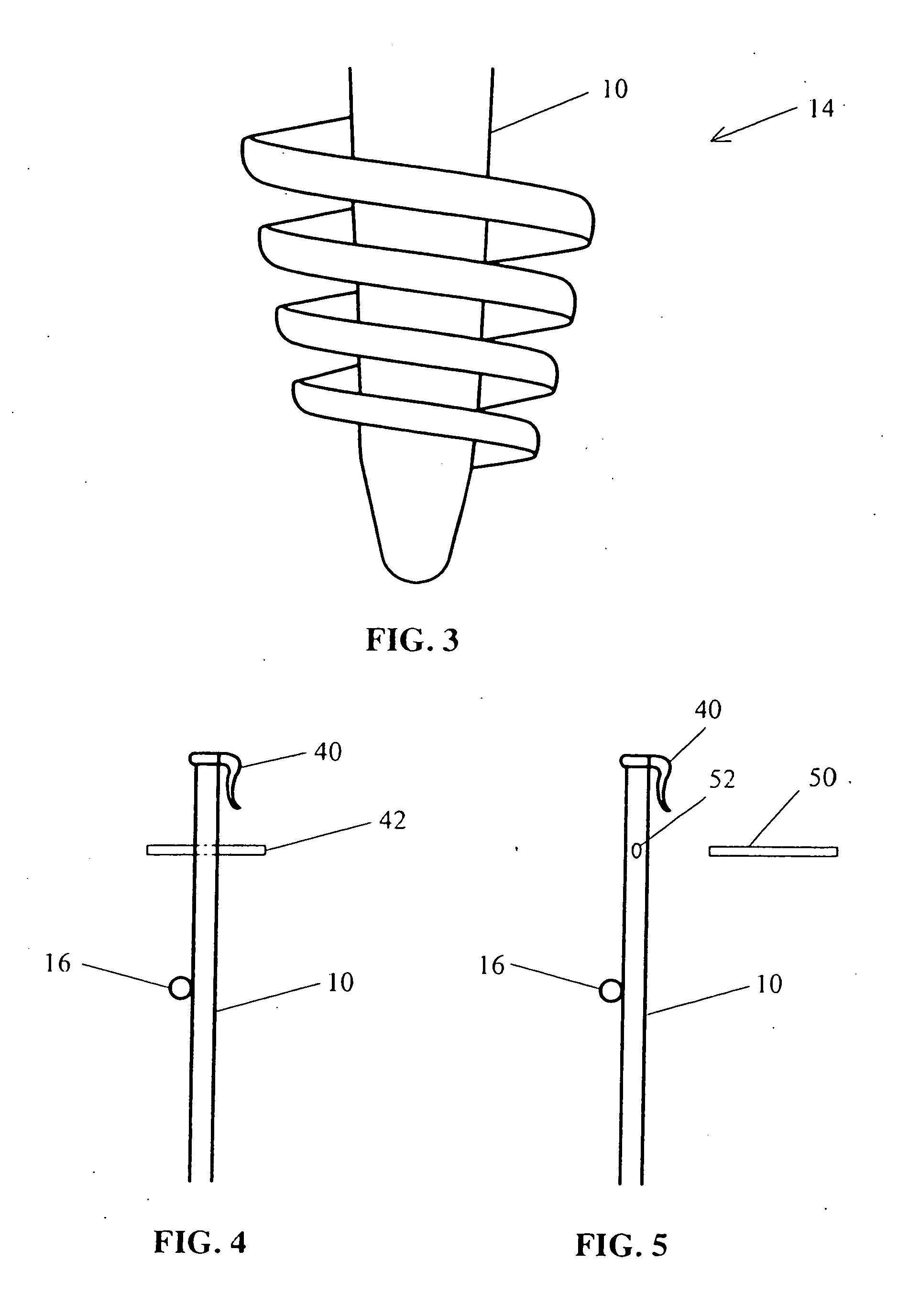
[0040] Referring now to the drawings, wherein like reference numerals indicate like elements, in FIG. 1 there is shown an embodiment of the beach umbrella or the like which may be of any desired size. As illustrated, shaft 10 comprises two ends. First end of shaft 10 is removably attached to canopy 12. First end of shaft 10 is tubular. Auger 14 is integrated with second end of shaft 10. There are many types of materials known by those of ordinary skill in the art, which could serve as appropriate composition of shaft 10. Examples of such materials include plastic, metal and the like. In a preferred embodiment shaft 10 is aluminum or titanium. Ring clip 16 is attached to shaft 10. In a preferred embodiment, ring clip 16 is attached on or about the midpoint of shaft 10. Ring clip 16 enables the removable attachment of items such as camera, bags, purse, ice chest and the like by way of an attaching means such as a clip or carabiner or the like. In an alternative embodiment, attaching m...


PUM


Abstract

The present invention relates generally to a beach umbrella with a lower shaft, having an improved anchoring means integral to the lower half of the shaft and an air pressure venting means that results in enhanced stability. According to the present invention, the anchoring means is an auger or spiral flange. The lower shaft is further optionally provided with a handle such as a cross bar, which in addition to the auger or spiral flange, eases insertion of the lower shaft of the umbrella into the sand.

Description

RELATED APPLICATION [0001] This application claims priority to U.S. Provisional Applications Ser. Nos. 60 / 686,940 and 60 / 686,939, filed Jun. 3, 2006, which are incorporated herein by reference in their entirety.FIELD OF INVENTION [0002] The present invention relates generally to improved beach umbrellas and similar products that are used at a beach, picnic, or outdoors generally having enhanced utility. More specifically, the present invention relates to a new beach umbrella having an improved anchoring means and an air pressure venting means, resulting in enhanced stability. BACKGROUND OF INVENTION [0003] There are as many cases of skin cancer as there are of all other cancers combined—about 1 million new U.S. cases per year. Indeed, the incidence of melanoma, the most deadly form of skin cancer, has steadily increased about 3% per year since 1981. The primary cause of skin cancer is chronic unprotected exposure to the sun and intense irregular exposures such as those that occur at...

Claims


Application Information

Patent Timeline
Patent Type & Authority Applications(United States)
IPC IPC(8): A45B3/00
CPCA45B23/00E04H12/2223A45C3/10
Inventor TANNER, ROBERTTANNER, BARBARA
Owner TANNER ROBERT
Learn More