Dual-array detector module

a detector module and detector array technology, applied in the field of dual-array detector modules, can solve the problems of increasing the repetition frequency of accelerators, increasing the radiation field intensity of the entire radiation imaging system, and difficult radiation shields, etc., and achieves the effects of simple structure, increased scanning speed of radiation imaging systems, and convenient mounting and maintenan

Active Publication Date: 2006-12-07
NUCTECH CO LTD
View PDF2 Cites 35 Cited by
  • Summary
  • Abstract
  • Description
  • Claims
  • Application Information

AI Technical Summary

Benefits of technology

[0015] According to the embodiments of the present invention, a detector module consisting of two detector arrays (the first detector array and the second detector array) are used in the radiation imaging system, so that the scanning speed of the radiation imaging system can be increased.
[0016] Since a heavy metal, plate is provided between the first detector array and the second detector array, with spacing heavy metal sheets being disposed between adjacent detectors in each of the first detector array and the second detector array, and heavy metal sheets are disposed between the mounting fame and the first and second detector array, the heavy metal plate, the spacing heavy metal sheets, and the heavy metal sheets includes, but are not limited to, lead sheet, tungsten alloy sheet, and tantalum sheet, the structure information about the inspected object will not be missed and the resultant image will not be distorted, so that the imaging quality can be improved greatly.
[0017] Further, the dual-array detector module according to the embodiments of the present invention is simple in structure, and convenient for mounting and maintenance.

Problems solved by technology

But in actual applications, increasing of the repetition frequency of the accelerator is limited, because there is technical difficulty, and on the other hand, it will increase the radiation field intensity of the entire radiation imaging system, so that the radiation shield becomes difficult and the power assumption of the entire radiation imaging system is increased.
Moreover, with the existing single-array detector, the utilization efficiency of the radiation field is low.
Increasing width of the sensitive region of each detector in the single-array detector will increase the pixel of the detector, which is disadvantageous to the identification of the fine object such as fine wire for the radiation imaging system, so that the structure information of the object to be inspected may be lost, thus degrading or deteriorating the imaging quality.

Method used


Image

  • Dual-array detector module
  • Dual-array detector module
  • Dual-array detector module

Examples


Embodiment Construction

[0021] Embodiments of the present invention will be described in detail with reference to the accompany drawings, the embodiments described herein are explanatory and illustrative and shall not be construed to limit the present invention. The same elements are denoted by like reference numerals throughout the following descriptions.

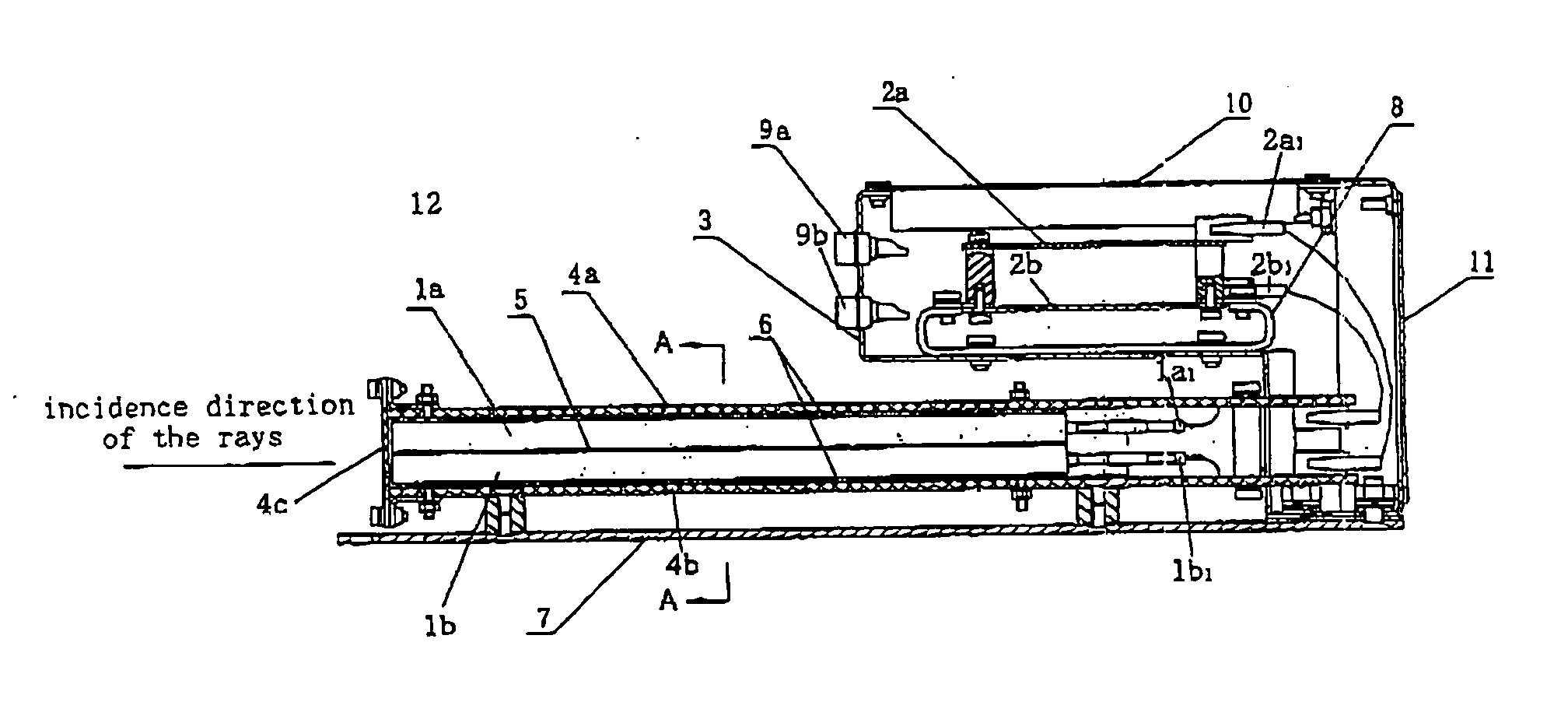
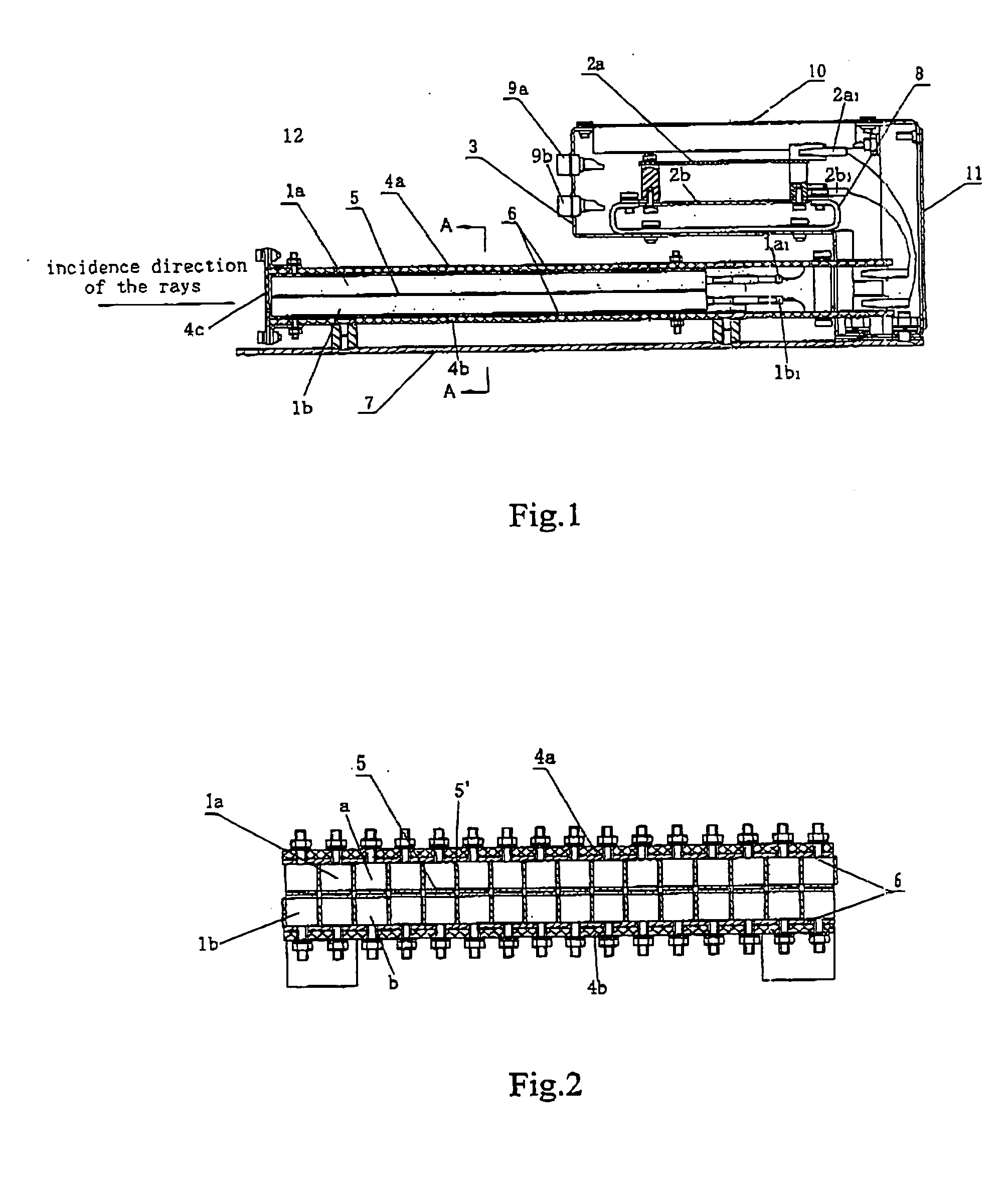
[0022] As shown in FIGS. 1 and 2, a dual-array detector module 12 according to an embodiment of the present invention comprises a first detector array 1a, a second detector array 1b, and a mounting frame 4. The first detector array 1a consists of a plurality of first detectors a and is arranged on a first surface (upper surface in FIG. 2) of a heavy metal plate 5. The second detector array 1b consists of a plurality of second detectors b and is arranged on a second surface (lower surface in FIG. 2) of the heavy metal plate 5, the second surface is opposite to the first surface. The first detector array 1a disposed on the first surface of the heavy metal ...


PUM


Abstract

The present invention discloses a dual array detector module adapted to radiation-imaging, comprising: a first detector array consisting of a plurality of first detectors and arranged on a first surface of a heavy metal plate; a second detector array consisting of a plurality of second detectors and arranged on a second surface of the heavy metal plate, the second surface is opposite to the first surface; and a mounting frame, in which the first detector array and the second detector array arranged on the first and second surfaces of the heavy metal plate respectively are mounted in the mounting frame. The dual array detector module according to the present invention is simple in structure and convenient for mounting and maintenance, so that a great economic benefit can be obtained by improving the structure simply and increasing a little of investment.

Description

BACKGROUND OF THE INVENTION [0001] 1. Technical Field of the Invention [0002] The present invention relates to a radiation inspection technology, and more particularly, to a dual-array detector module used in radiation imaging system. [0003] 2. Description of the Related Art [0004] In the prior art, a plurality of detectors used in radiation imaging are arranged in a single array so as to form a single-array detector module. The single-array detector module is relatively simple in manufacture process and image reconstruction. [0005] In a radiation system using pulsed X-rays generated by an electron accelerator as a radiation source, in order to prevent the image from distorting and avoid missing of the information about the inspected object, the following relationships should be satisfied: the maximum speed at which the object to be inspected is scanned is in proportion to the repetition frequency of the accelerator and the width of the sensitive region of the array detector. But in...

Claims


Application Information

Patent Timeline
Patent Type & Authority Applications(United States)
IPC IPC(8): G01T1/00
CPCG01N23/04
Inventor LI, YUANJINGLI, SHUWEIZHANG, QINGJUNMIAO, QINGWENGAO, WENHUANDAI, ZHUDEJIANG, NIANMING
Owner NUCTECH CO LTD
Why Eureka
Try Eureka