
Method of manufacturing a high sag lens and a lens manufactured by using the same method

a manufacturing method and high sag technology, applied in the field of manufacturing a high sag lens and a lens, can solve the problems of difficult to manufacture high sag or sag having a height of hundreds of m, limited conventional methods, and difficult to achieve aspheric surface, etc., to achieve enhanced lens quality and high sag

Inactive Publication Date: 2006-12-07
SAMSUNG ELECTRO MECHANICS CO LTD
View PDF11 Cites 21 Cited by
  • Summary
  • Abstract
  • Description
  • Claims
  • Application Information

AI Technical Summary

Benefits of technology

[0016] The present invention has been made to solve the foregoing problems of the prior art and it is therefore an object of the present invention to provide a method of manufacturing a high sag lens, which does not require correction of a lens surface by ensuring polymer shrinkage to occur in a region other than the lens surface and significantly enhances lens quality by preventing bubbles from remaining in the lens, and a lens manufactured thereby.

Problems solved by technology

But such conventional methods have limitations as described below.
This renders it difficult to manufacture a high sag or a sag having a height of hundreds of μm.
Also, in processing a mold via laser beam, an aspheric surface is hardly attainable and has limits in manufacturing the aspheric surface.
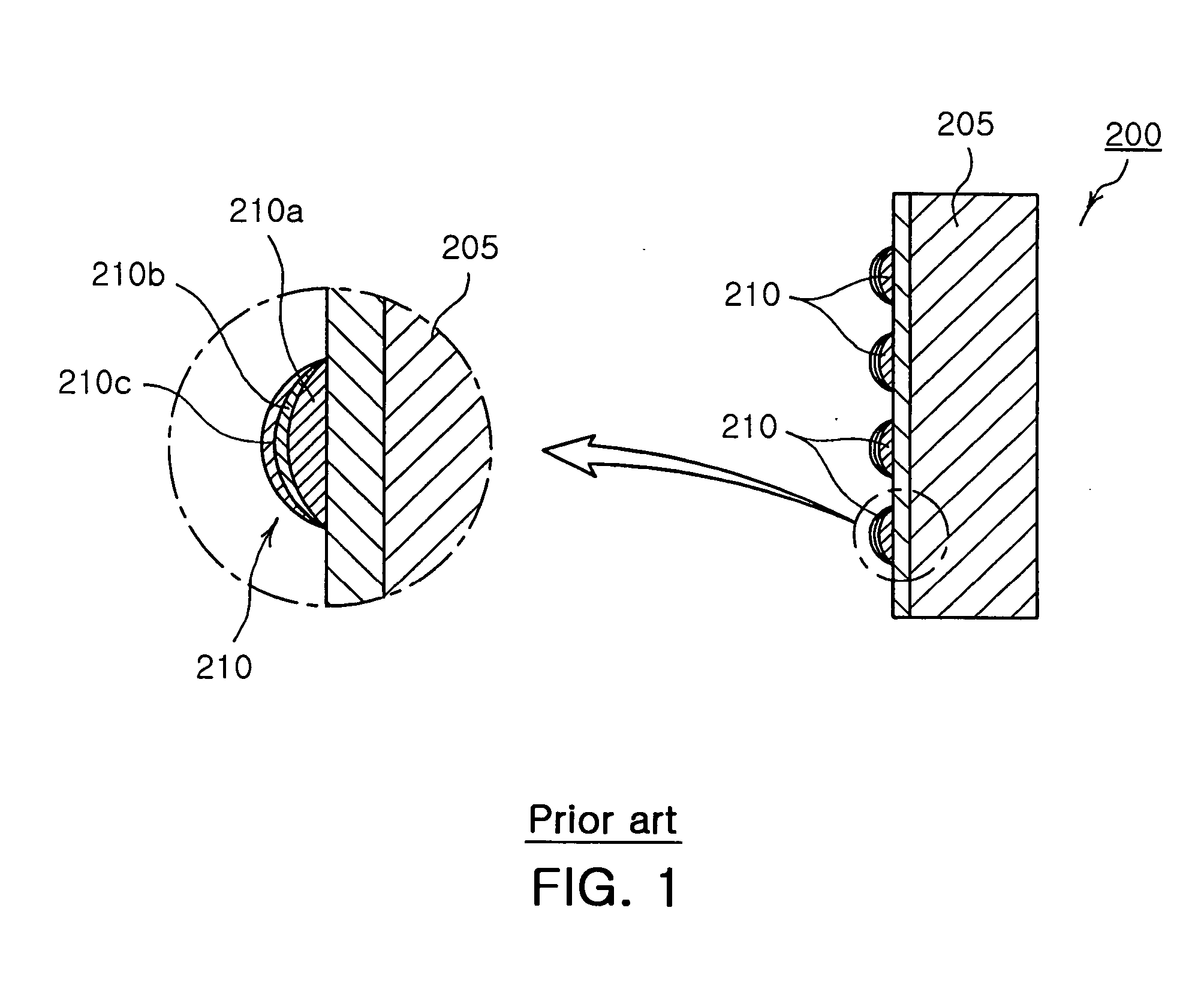
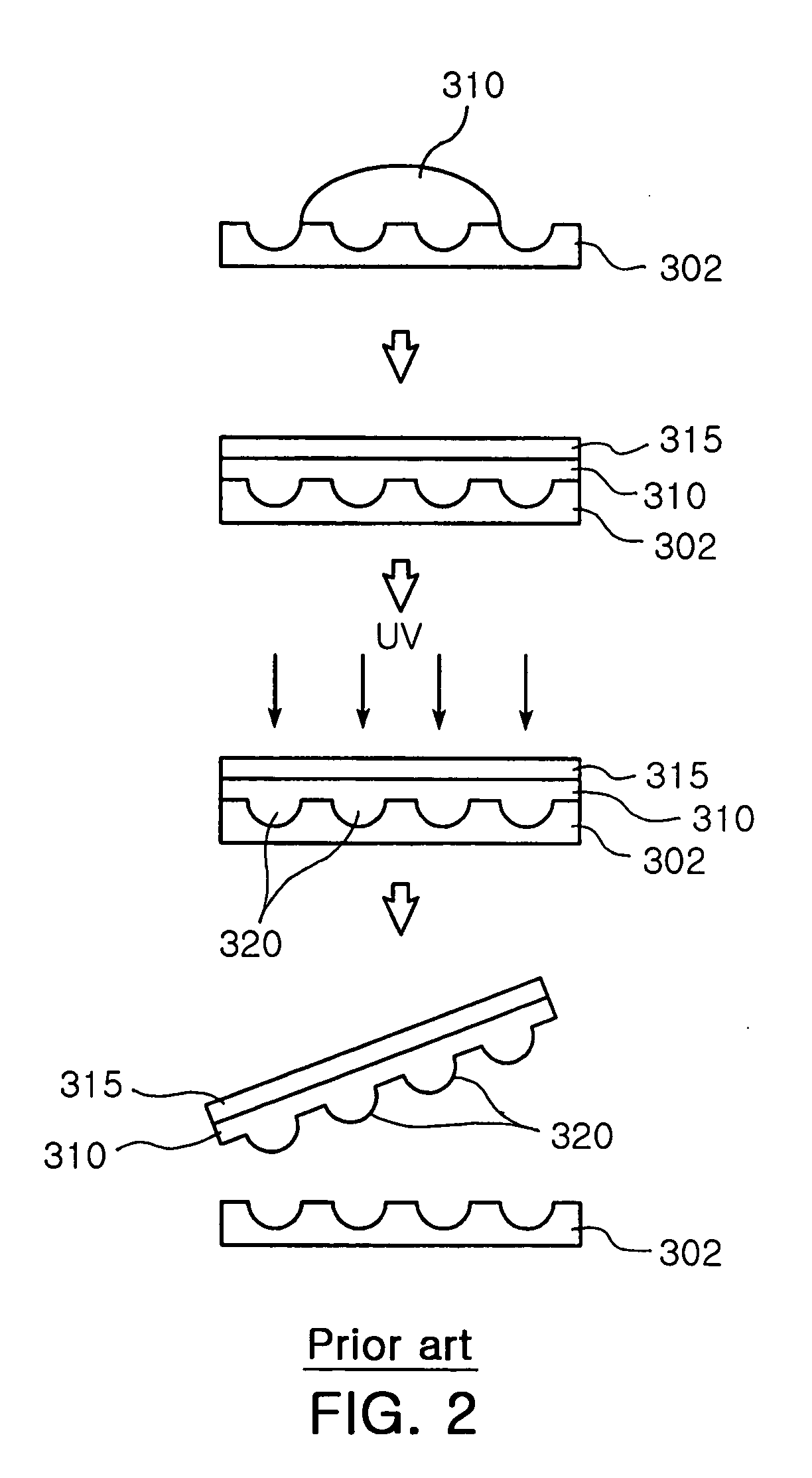
But in case where a lens section 210 is formed on a substrate 205 by repeated replication of at least twice, an entire process such as polymer drop, compression, UV curing and release of repeated replication require a considerable amount of work time.
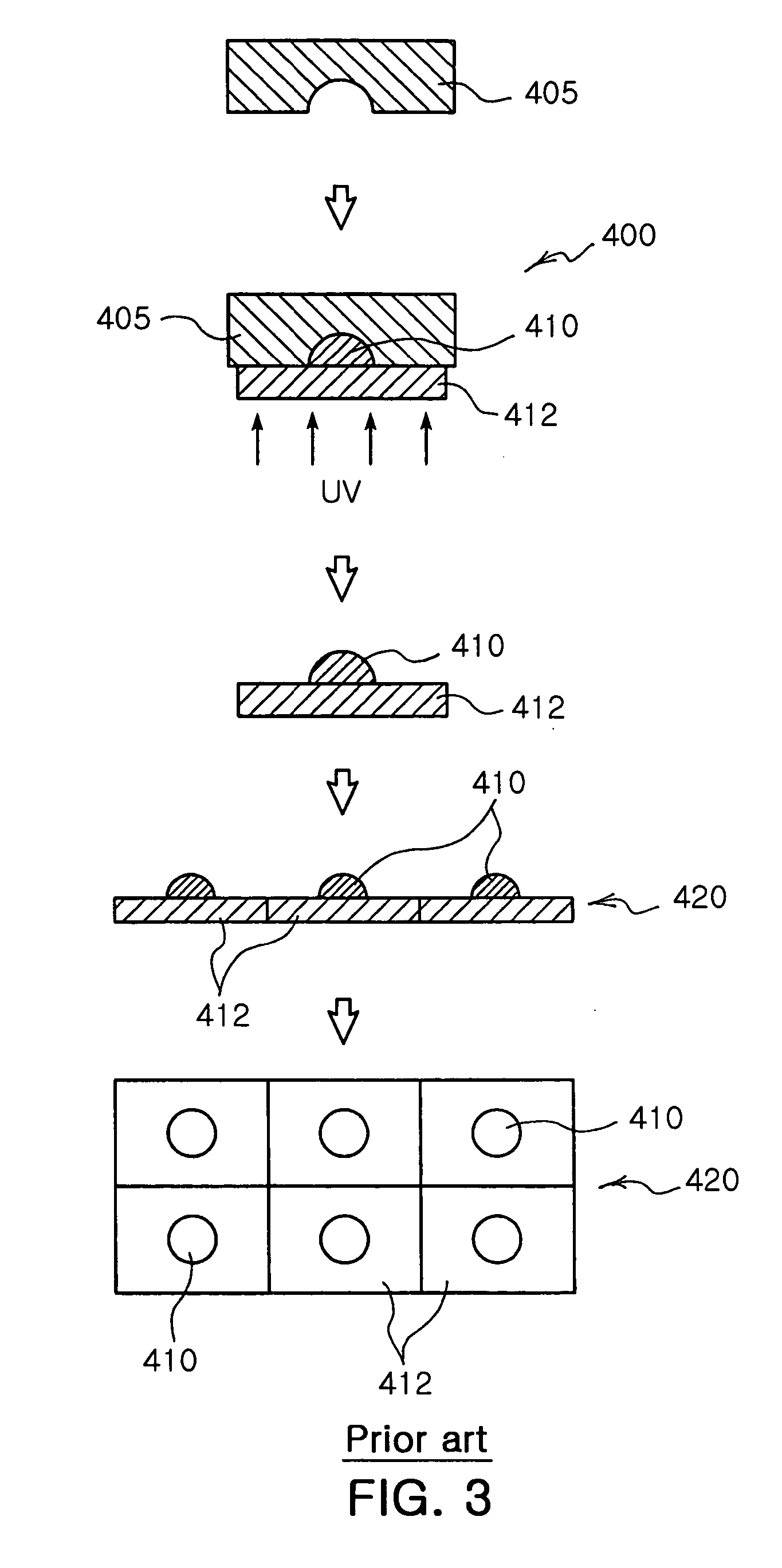
However, such conventional technologies have problems in a manufacturing process.
Therefore in case of completed curing, polymer contracts most intensively on the spherical lens surface P. This leads to defective curvature and form.
Also, during curing of polymer of the lens section, bubbles may build up.

Method used


Image

  • Method of manufacturing a high sag lens and a lens manufactured by using the same method
  • Method of manufacturing a high sag lens and a lens manufactured by using the same method
  • Method of manufacturing a high sag lens and a lens manufactured by using the same method

Examples


Embodiment Construction

[0036] Preferred embodiments of the present invention will now be described in detail with reference to the accompanying drawings.

[0037] In a method of manufacturing a high sag lens (designated with the reference sign 1) according to the invention, as shown in FIGS. 5a to 5c, first, polymer 15 is injected into a mold 10 having a plurality of grooves 10a and cured by ultraviolet ray to form a plurality of lens sections 20 (see FIG. 5a). The mold 10 is machined by a diamond turning machine (DTM), which ensures easy manufacture of an aspherical lens and enables manufacture of a high sag lens. That is, the grooves 10a formed on the mold 10 have a depth of hundreds of μm, and thus just one molding allows a depth of a high sag lens at one time.

[0038] Further, polymer 15, which is injected into the mold 10, is cured by ultraviolet ray with its surface exposed to air. In this case, polymer positioned in the grooves 10a of the mold 10 is cured most slowly at an interface with air. This is ...


PUM

PropertyMeasurementUnit
Compositionaaaaaaaaaa
Shrinkageaaaaaaaaaa
Optical propertiesaaaaaaaaaa

Abstract

The invention provides a method of manufacturing a high sag lens and a lens manufactured thereby. According to the invention, in manufacturing a lens, a polymer lens section made of ultraviolet cured resin is formed on a substrate. Polymer is injected into a mold having a plurality of grooves and then cured by ultraviolet ray to form a plurality of lens sections. Thereafter, a substrate is adhered integrally to a back side of the lens section. Finally, the mold is released from the lens section to produce a lens array. The invention eliminates a need to correct a lens surface resulting from polymer shrinkage and enhances quality of the lens. Also, the invention allows manufacture of the lens without repeating a replication method and dramatically increases work productivity.

Description

CLAIM OF PRIORITY [0001] This application claims the benefit of Korean Patent Application No. 2005-48006 filed on Jun. 3, 2005 in the Korean Intellectual Property Office, the disclosure of which is incorporated herein by reference. BACKGROUND OF THE INVENTION [0002] 1. Field of the Invention [0003] The present invention relates to a method of manufacturing a high sag lens and a lens manufactured thereby. More particularly, the present invention relates to a method of manufacturing a high sag lens which enhances lens quality without any need to correct a lens surface resulting from polymer shrinkage, and drastically increases work productivity due to its manufacture without repeated replication, and a lens manufactured thereby. [0004] 2. Description of the Related Art [0005] Conventionally, a lens array was directly produced via laser beam or formed by an etching or reflow method using a pattern. A lens array was used to fabricate a Ni master mold via Ni electro-plating. Then the Ni ...

Claims


Application Information

Patent Timeline
IPC IPC(8): B29D11/00
CPCB29D11/00365G02B3/0018G02B3/02G02B3/0031G02B3/0025B29D11/00298B29D11/00442B29C35/08B29D11/00
Inventor JIN, YOUNG SUJEONG, HO SEOPSHIN, DONG IK
Owner SAMSUNG ELECTRO MECHANICS CO LTD
Learn More