Suspension system for a vehicle

a suspension system and vehicle technology, applied in the direction of rigid suspensions, suspensions, resilient suspensions, etc., can solve the problems of poor ride quality for vehicle occupants, low suspension system performance, and poor suspension quality

Inactive Publication Date: 2006-12-07
TIMBREN INDS
View PDF11 Cites 22 Cited by
  • Summary
  • Abstract
  • Description
  • Claims
  • Application Information

AI Technical Summary

Benefits of technology

[0007] It is an object of the present invention to obviate or mitigate at least one disadvantage of previous suspension systems for vehicles.

Problems solved by technology

For many years, vehicle manufacturers preferred this design due to its simplicity, but leaf springs suffer from various disadvantages.
These disadvantages include a poor quality of ride for the vehicle occupants since a leaf spring suspension system contains little or no energy absorbing medium to dampen shocks and to reduce the natural frequency of vibration of the sprung mass (which is the mass of the vehicle supported on the suspension system).
Furthermore, the suspension system is typically quite noisy since there are many moving joints and parts.
Another disadvantage of a leaf spring suspension system is that the system comprises many components which need to be installed together which leads to a need for more regular maintenance.
Also, over time, leaf springs deform permanently and once a leaf spring is deformed, its length also changes which causes an equalizer bar to permanently lean to one side reducing the operating range of the suspension system.
With air suspension systems, these are generally less reliable since they are subject to air leaks which may take place within fittings, the tubing, height control valves, inflate / deflate valves, air compressors or the air springs themselves.
The performance of an air suspension is dependent on the ability of the system to regulate the air pressure in the air springs which is not an easy task.
If there is too much pressure in the air springs of the suspension system, the ride becomes rough but if there is not enough pressure in the air springs, the suspension system is ineffective.
Furthermore, due to the size of air springs, they are not adaptable for some applications.
Also, for vehicles using air suspension systems, thicker wall axles are preferred which result in heavier and more expensive axles being used.
Maintenance and the replacement of damaged or worn parts in a rubber torsion-bar suspension system is also quite difficult such that when a part requires repair, the entire system is generally replaced.
The suspension system is also large and bulky which makes it more difficult to store and ship the rubber torsion-bar suspension systems.
Furthermore, when the crank arm of the torsion-bar suspension system acts as a cantilever beam, the crank arm experiences combined bending and torsion stresses.
However, these short crank arms require a large range of rotation to provide an adequate amount of spindle travel and therefore, when combined with a predetermined camber causes a wide range of change in toe-in angle.
This change in toe-in angle causes an increase in the amount of scrubbing, chafing and / or wearing of tires especially when the vehicle is in a loaded condition.

Method used


Image

  • Suspension system for a vehicle
  • Suspension system for a vehicle
  • Suspension system for a vehicle

Examples


Embodiment Construction

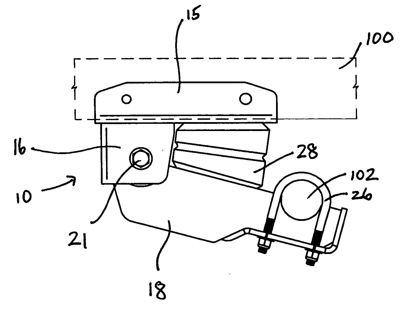
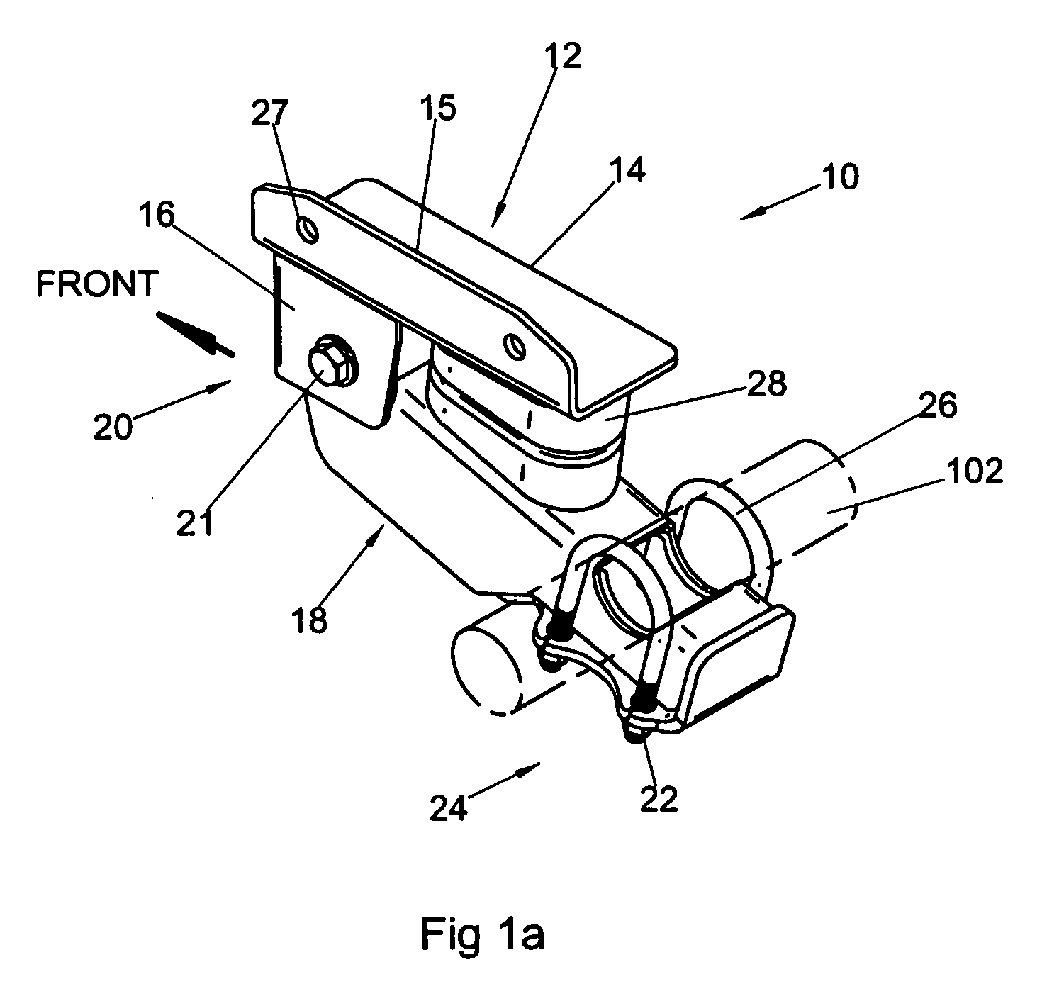
[0028] Generally, the present invention provides a novel suspension system for a vehicle.

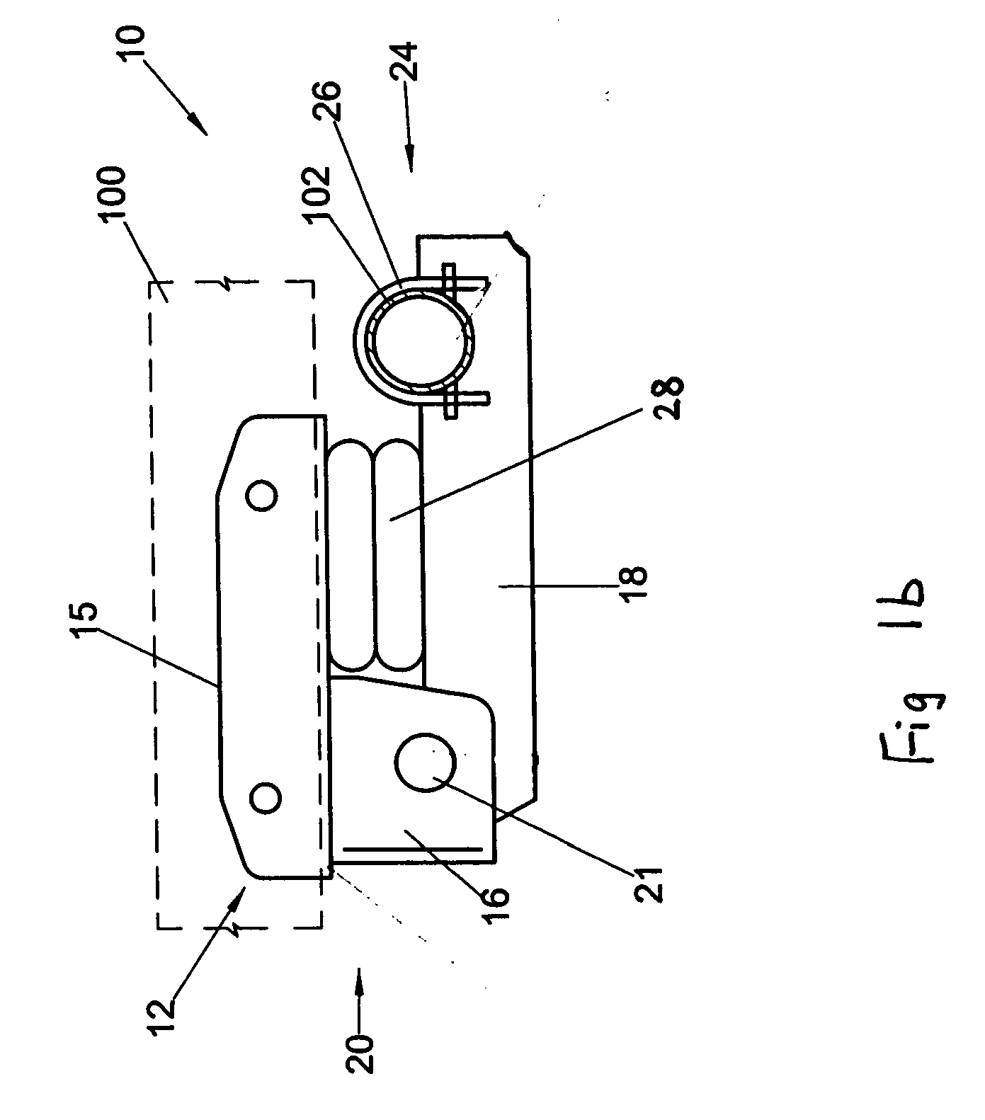
[0029]FIGS. 1a to 1c provide, respectively, a perspective view and two side views of a suspension system which is to be installed at one end of an axle of a vehicle. FIG. 1b is a side view of the suspension system with the elastomer spring compressed and FIG. 1c is a side view of the suspension system with the elastomer spring uncompressed.

[0030] In the present application, the term suspension system has been used to describe the suspension system for one end of a vehicle axle. However, as will be appreciated by one skilled in the art, a pair of suspension systems are generally mounted at opposite ends of an axle to provide adequate support and stability for a vehicle. The axle is a fixed bar or beam with bearings at its ends to mount the axle to a tire, or wheel, at each end about which the tires rotate. Although it is not common for only one suspension system to be mounted to an axle, this e...


PUM


Abstract

A suspension system for wheeled vehicles, particularly trailers, that is mounted underneath the vehicle frame and forward of the axle (in case of a single axle suspension) and both forward and rearward of axles (in case of a tandem axle suspension). The suspension system at each side of the vehicle frame comprises a hanger, a control arm and an elastomer spring. The hanger has a support bracket and a hanger channel and is the frame bracket connecting the suspension to the vehicle frame. The elastomer spring biases the control arm and the hanger and therefore isolates the vibration of the suspended portion of the vehicle (the sprung mass) from that of the axle(s) and wheels (the unsprung mass).

Description

FIELD OF THE INVENTION [0001] This invention relates generally to suspension systems. More particularly, the invention relates to a suspension system for a vehicle such as a light, or medium duty trailer. BACKGROUND OF THE INVENTION [0002] The use of suspension systems for wheeled vehicles such as light to medium duty trailers is well known. Suspension systems are generally a set of components, including springs and shock absorbers, which suspend the vehicle above the wheels to isolate vibration of the sprung mass. Many different suspension systems are available for vehicle owners with the most common types of suspension systems being leaf spring suspensions, air suspensions and / or rubber-torsion-bar suspensions. [0003] Leaf spring suspensions are well known and have been used for a long time. In general, if a solid axle connects the rear wheels of the vehicle, the suspension is usually quite simple and is based on a leaf spring suspension system. The leaf spring clamps directly to ...

Claims


Application Information

Patent Timeline
Patent Type & Authority Applications(United States)
IPC IPC(8): B60G9/00B60G5/00
CPCB60G5/02B60G9/003B60G11/22B60G2204/125B60G2200/31B60G2202/143B60G11/24
Inventor HERON, ARNOLD J.REZANIA, PARTO
Owner TIMBREN INDS
Why Eureka
Try Eureka