
Long range and safer electric vehicle configuration

a technology of electric vehicles and configurations, applied in the direction of electric propulsion mounting, electric devices, battery/cell propulsion, etc., can solve the problems of unfavorable center of gravity and vehicle handling, high aerodynamic drag, and higher energy consumption, so as to reduce aerodynamic drag and narrow the wheel base. the effect of the width and the safety of passengers

Inactive Publication Date: 2006-02-16
KEJHA JOSEPH B
View PDF4 Cites 12 Cited by
  • Summary
  • Abstract
  • Description
  • Claims
  • Application Information

AI Technical Summary

Benefits of technology

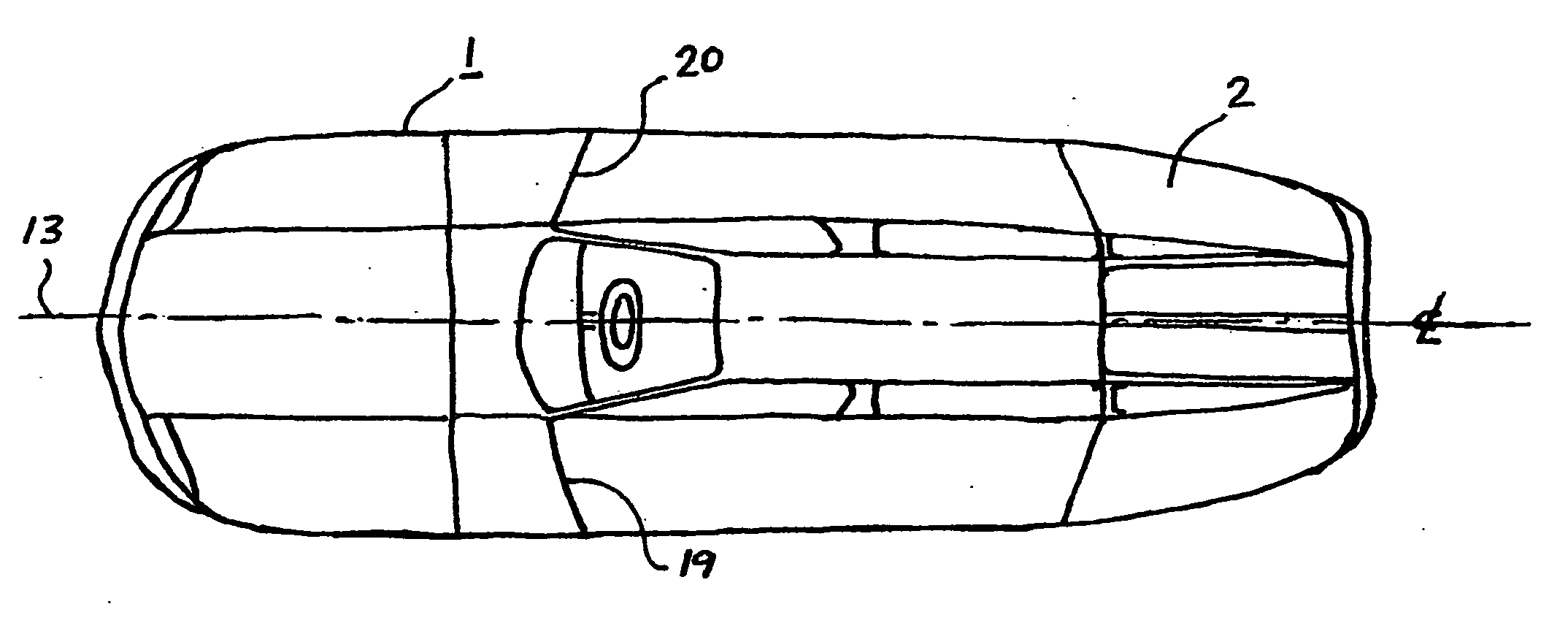
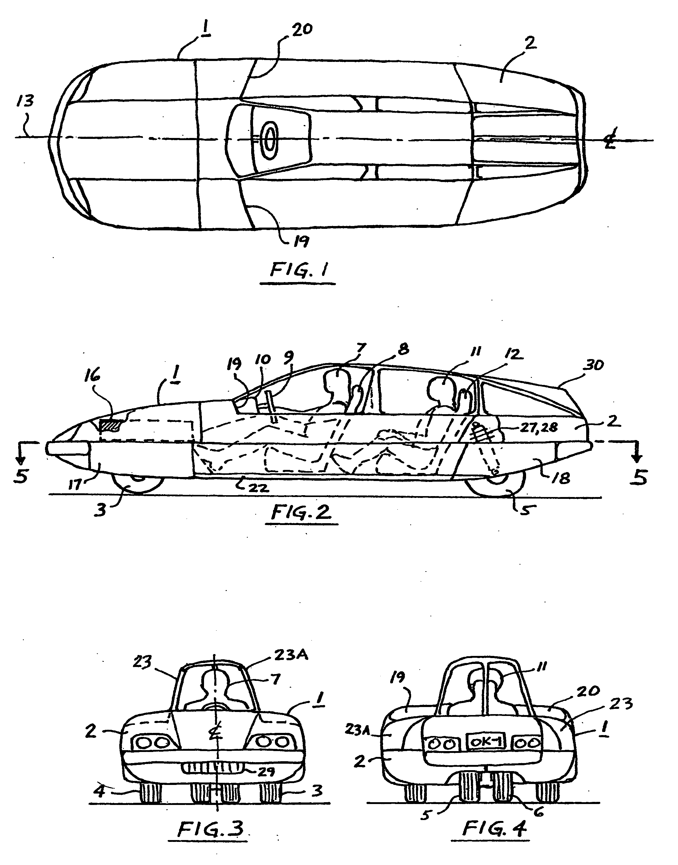
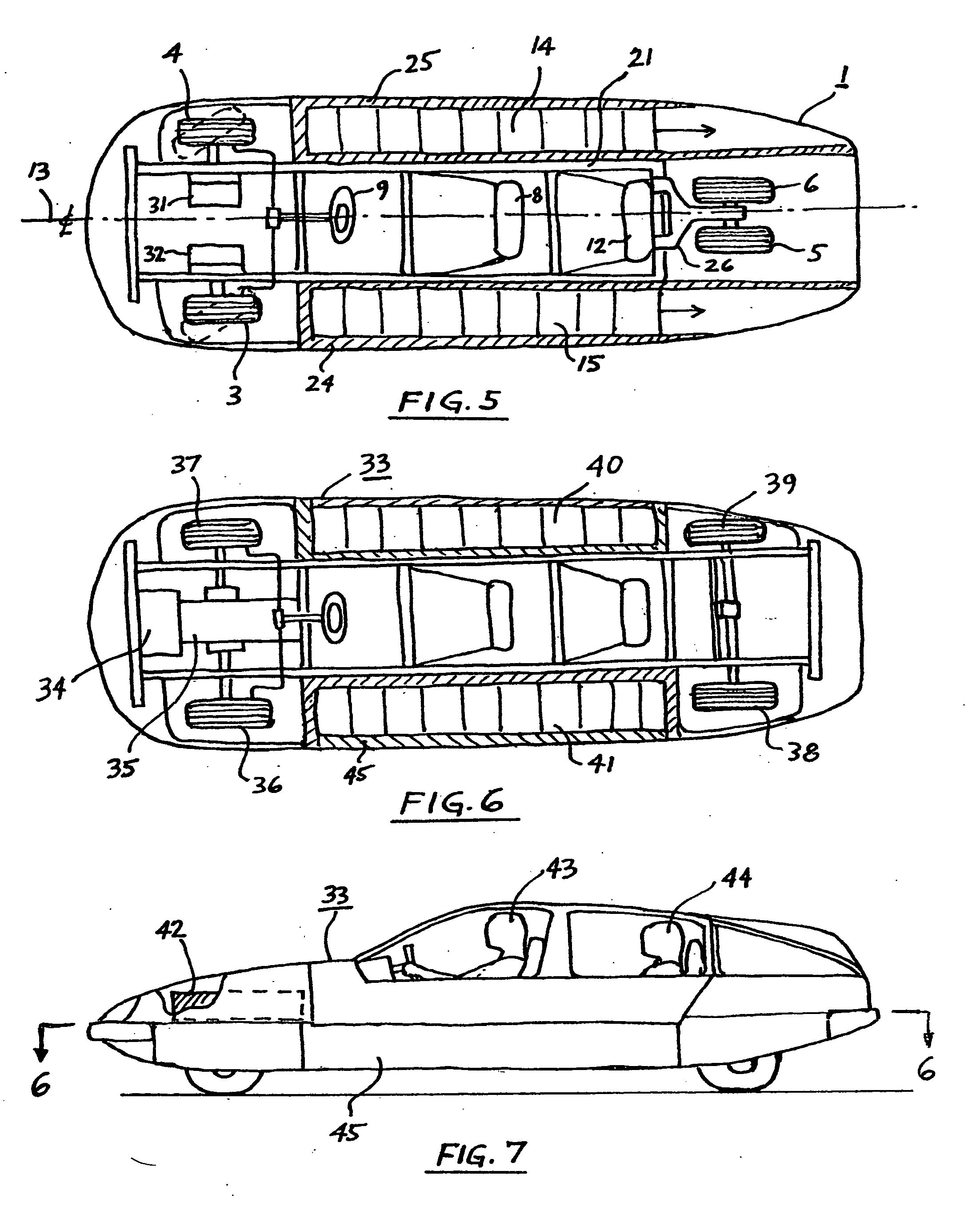
[0032] It has now been found that low drag, lightweight, highly energized and safer electric vehicles, of at least three wheels, for at least two passengers can be made by seating the driver and the passenger (or passengers) in a tandem configuration, one behind the other, approximately on the imaginary longitudinal center-line of symmetry-line of the vehicle, which permits narrowing the width of the wheel base and thus it makes possible to cover the wheels with removable or hinged side panels, while maintaining the original three or four wheeled vehicle body width (as with side by side seating), and which also permits decreasing the frontal area of the windshield by 50% (percent), and the frontal area of the vehicle by approximately 25% (percent). Smoothing the sides of the vehicle by said panels and maintaining a streamlined body shape the aerodynamic drag is substantially reduced; in addition, locating two battery packs in rows on both sides of the passengers and one battery pack in the front of the vehicle increases the safety of the passengers by protecting them with the batteries' mass. Lowering the total weight of the vehicle and further safety improvements can be achieved by using magnesium metal for the vehicle body frame, and / or cage construction, by using ultra-high molecular weight polyethylene fibers with a polyester or vinylester resin, and preferably a fire retardant paper or metal such as aluminum honeycomb, or foam for the body panel construction, and by using lightweight, pressure-airless tires.
[0033] It has also been found that the range of the electric vehicle can be extended by using an additional, internal combustion based propulsion and electricity generating system, such as engine / generator, which is fueled by non-polluting hydrogen, preferably produced on demand only, for safety, by the electrolysis of water and / or by other means carried in the vehicle, and that the hydrogen component as fuel can be used also for the vehicle heating, cooling system and for recharging the batteries; and that the hydrogen fuel can be replenished also by an on-board electrolyzer refilled with water and connected to an outside electric power source anywhere, and that said hydrogen may be stored in a low pressure tank filled with a metal hydride or a lightweight carbon, such as graphite.
[0035] The principal object of the invention is to provide a safer hydrogen-electric hybrid vehicle construction which can carry at least one passenger, which has at least three wheels, which has a low aerodynamic drag, is lightweight and has a low energy consumption and long range.
[0038] A further object of the invention is to provide electric vehicle construction, which is easy and economical to manufacture.
[0039] A further object of the invention is to provide electric vehicle construction, which has improved vehicle maneuvering and steering.
[0040] A further object of the invention is to provide electric vehicle construction, which has a quiet ride.

Problems solved by technology

However, this structure contributes to high aerodynamic drag and resultant higher energy consumption, especially at speeds above 35 miles per hour.
The battery packs for electric vehicles have usually been located in the front or back of the vehicle, which unfavorably affects the center of gravity and vehicle handling, or in some instances, the battery packs have been mounted on the centerline of the vehicle in a tunnel.
The center tunnel construction further contributes to increased body width, placing the passengers further apart and thus increasing the frontal area, aerodynamic drag, weight and energy consumption.
The center tunnel construction also makes servicing of the batteries more difficult, due to their limited access.
GB Patent #2,254,055 of Bothwell discloses a four wheeled vehicle with tandem seating of the two passengers, but does not teach location of batteries or fuel cells in lower side compartments, lengthwise between the wheels, outside of the passenger compartment.
Large electric vehicle batteries in this location would adversely impact center of gravity and steering of the vehicle.
JP-6-156316 patent of Suzuki teaches an electric automobile having tandem seating of the passengers, but clearly shows less aerodynamic vehicle with location of batteries under the rear seat—(not on sides), which results in larger (higher) frontal area, increased drag, reduced safety of the driver during frontal impact and an unstable vehicle with the center of gravity close to the rear wheels.
Patterson does not teach anything about streamlining of the mirrors and air drag reduction, and provides very limited rear view angle due to the narrowness of his mirror, and the rear part of the window frame is obstructing the view directly rearward.
U.S. Pat. No. 2,757,018 of Galla teaches a hinged fender skirt covering the rear wheel, but does not teach top hinged panels covering the front wheels.
The front wheels of Galla's conventional vehicle protrude from the body during steering and thus would interfere with the front panels.
It would not be obvious to use honeycomb in the sides of the vehicle, because Jensen's vehicle does not provide for thick sides because it does not have low side batteries and tandem seating of the passengers.
There is no reason to add thickness of Jensen's vehicle side, since it would only increase the air drag and weight.
While aluminum metal is lightweight, it is not the most lightweight structural metal.
Carbon fibers are brittle and dangerous in a crash, as they have low impact resistance, and aramid fibers are not the most lightweight fibers.
Spacecraft structures sometimes use welded magnesium extrusions, which are expensive due to requirement of special inert atmosphere for welding, the need for complex welding fixtures and heat treatment after welding to relieve stress in the structure.
Janotik also does not teach a vehicle body frame made of magnesium alloy, and uses an adhesive in combination with crimping to join together only frame subassemblies, not all individual elements.
U.S. Pat. No. 3,617,364 of Jarema discloses a plastic layer on a foam core, but does not teach composite sandwich construction of body panel with a metal foam core.
The prior art electrical vehicles often have high pressure air filled tires, which can blow out and cause accidents.
Since the electric motors used in prior art vehicles do not generate appreciable quantities of heat and because the use of electricity for heating and cooling of the vehicle passenger compartment may be impractical due to the high energy drain on the batteries, prior art electric vehicles use auxiliary gasoline, diesel or kerosene fueled heating / cooling systems, but these systems continue pollution of the atmosphere and defeat the non-pollution purpose of electric vehicles.
In addition, prior art electric vehicles have very limited ranges, not only because of their body weight and high drag, but also because they utilize low specific energy density batteries.
Hybrid electric vehicle construction has been proposed, but the non-electric portion is not free from atmospheric pollution.
Dufour does not teach non-polluting, hydrogen generating system which is consuming only water, or only water and hydrogen.
U.S. Pat. No. 4,112,875 of Laumann et al. discloses a hydrogen-oxygen fueled, closed cycle internal combustion engine system in combination with solar cells, and which uses a pressurized noble gas, such as argon, as a working fluid, and which stores hydrogen and oxygen gases in storage devices under high pressure, which is very dangerous, heavy and space demanding.
Such system would be also too heavy and bulky, thus limiting the range and would be difficult to seal in a vehicle.
However, all prior art reactor systems produce a waste material which must be disposed of, and are dangerous to handle due to highly flammable hydrides when exposed to moisture or moist air.
There is also virtually no infrastructure available for these metal hydrides.

Method used


Image

  • Long range and safer electric vehicle configuration
  • Long range and safer electric vehicle configuration
  • Long range and safer electric vehicle configuration

Examples


Embodiment Construction

[0072] When referring to the preferred embodiments certain terminology will be utilized for the sake of clarity. Use of such terminology is intended to encompass not only the described embodiment, but also all technical equivalents which operate and function in substantially the same way to bring about the same results.

[0073] The electric vehicle and for example two passenger electric vehicle comprises, a body which is riding on three, four or more wheels with a steering and braking system, two seats, and at least one electric motor with a controller and a transmission or a reduction gear box connected to the wheels through the drive axles, at least one battery pack to store the electric energy, an instrumentation package and various lights.

[0074] The optional equipment may consist of an electric charger or a solar cell charger for the batteries, a heating and cooling system of the passenger enclosure, a cooling system of the electric motor and batteries, an air bag, various elect...


PUM


Abstract

An electric vehicle which carries at least two passengers, which has at least three wheels, said passengers sitting in tandem and most of the batteries or fuel cell systems are located on the sides of the passengers. The vehicle has an aerodynamically shaped body with substantially reduced frontal area and drag. The body is lightweight, made from shock absorbing materials and structures, and has pressure-airless tires, which enhances the safety of the passengers. The vehicle also includes an advanced electric hybrid propulsion system and various additional optional features and systems.

Description

CROSS REFERENCE TO RELATED DOCUMENTS [0001] This application is continuation in part of a prior co-pending patent application of Joseph B. Kejha, Ser. No. 09 / 350,713 filed Jul. 9, 1999, entitled HYDROGEN-ELECTRIC HYBRID VEHICLE CONSTRUCTION”, [0002] which is continuation in part of a prior patent application of Joseph B. Kejha, Ser. No. 08 / 950,445 filed Oct. 15, 1997, entitled “LONG RANGE AND ULTRALIGHT ELECTRIC VEHICLE”, now abandoned, which is continuation in part of a prior patent application of Joseph B. Kejha, Ser. No. 08 / 373,090, filed Jan. 17, 1995, entitled “LONG RANGE AND SAFER ELECTRIC VEHICLE CONSTRUCTION” now abandoned, and which is related to a prior Disclosure Document of Joseph B. Kejha, Ser. No. 322,973, filed Jan. 12, 1993, entitled “LONG RANGE AND SAFER ELECTRIC VEHICLE CONSTRUCTION”, which is related to a prior Disclosure Document of Joseph B. Kejha, Ser. No. 298,996, filed Jan. 27, 1992, entitled “LOW DRAG, LIGHTWEIGHT AND SAFER ELECTRIC VEHICLE CONSTRUCTION”. BA...

Claims


Application Information

Patent Timeline
Patent Type & Authority Applications(United States)
IPC IPC(8): B60K1/00B60K6/52B60K7/00
CPCB60K1/02Y02T10/7077B60K6/52B60K7/0007B60K17/043B60K2007/0046B60K2007/0092B60L11/123B60L11/126B60L11/14B60L11/1877B60L2220/46B60L2260/28B62D23/005B62D29/008B62D31/003Y02T10/6217Y02T10/6234Y02T10/6265Y02T10/7005Y02T10/705B60K6/442B60K1/00B60K7/00B60K2015/03315B60K1/04B60K17/356B60K2001/001B60K2001/005B60K2001/006B60K2001/0438B60K2001/0455B60K2001/0477B60K2001/0494B60K2015/0638B60Y2200/112B60Y2200/91B60Y2200/92B60K6/48B60L50/61B60L50/62B60L50/16B60L50/66Y02T10/62Y02T10/70Y02T10/7072
Inventor KEJHA, JOSEPH B.
Owner KEJHA JOSEPH B
Learn More