Pneumatic tire

a technology of pneumatic tires and pneumatic discs, which is applied in the direction of vehicle components, transportation and packaging, non-skid devices, etc., can solve the problem that the tires disclosed in the publication tend to produce a large pumping noise on the paved road, and achieve the effect of excellent performance in mud terrain and quiet rid

Active Publication Date: 2015-10-01
SUMITOMO RUBBER IND LTD
View PDF7 Cites 9 Cited by
  • Summary
  • Abstract
  • Description
  • Claims
  • Application Information

AI Technical Summary

Benefits of technology

[0006]The present invention has been worked out in the light of the circumstances described above, and has a main object of providing a pneumatic tire designed for excellent performance in mud terrain and quiet ride on paved road.
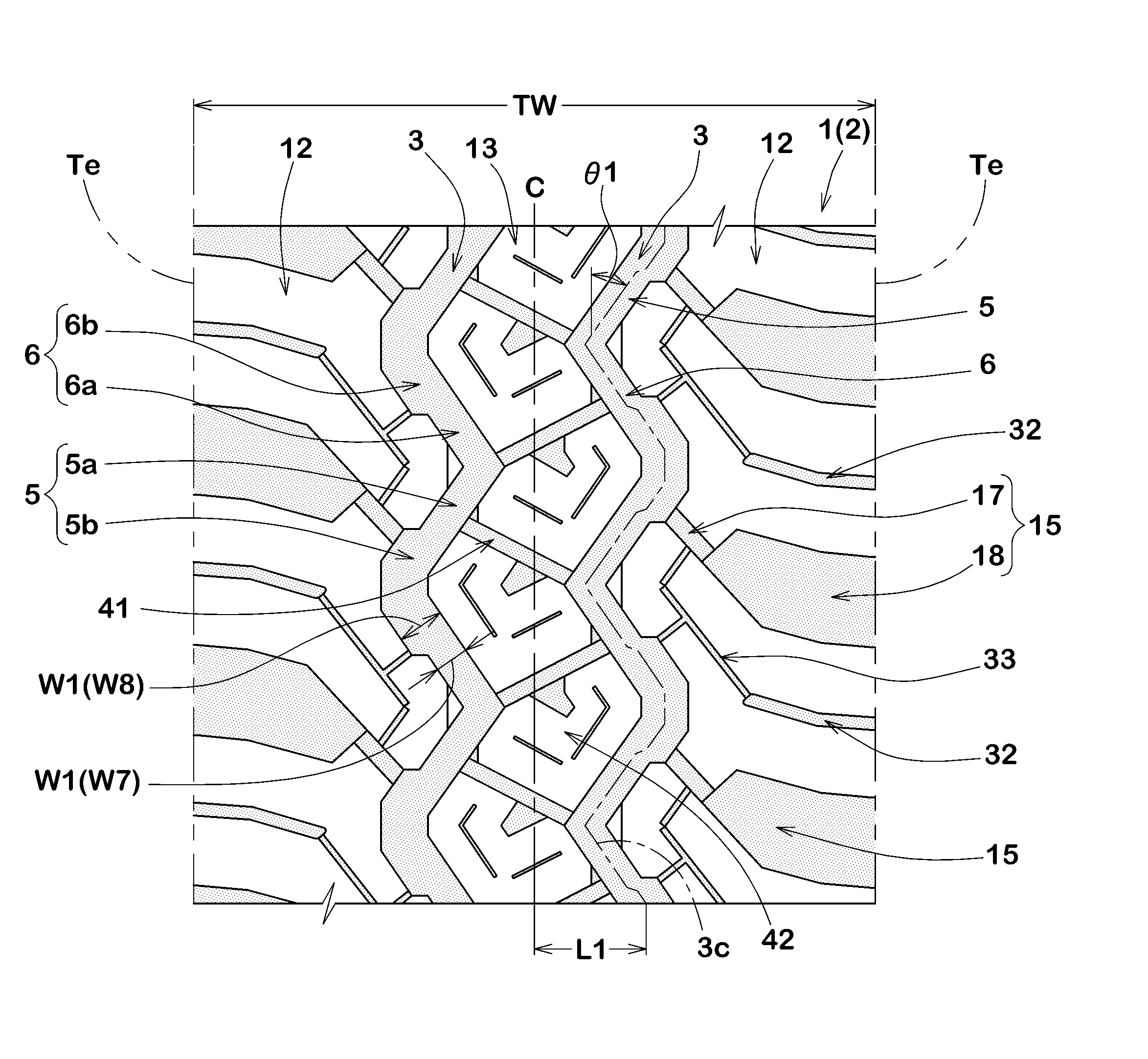
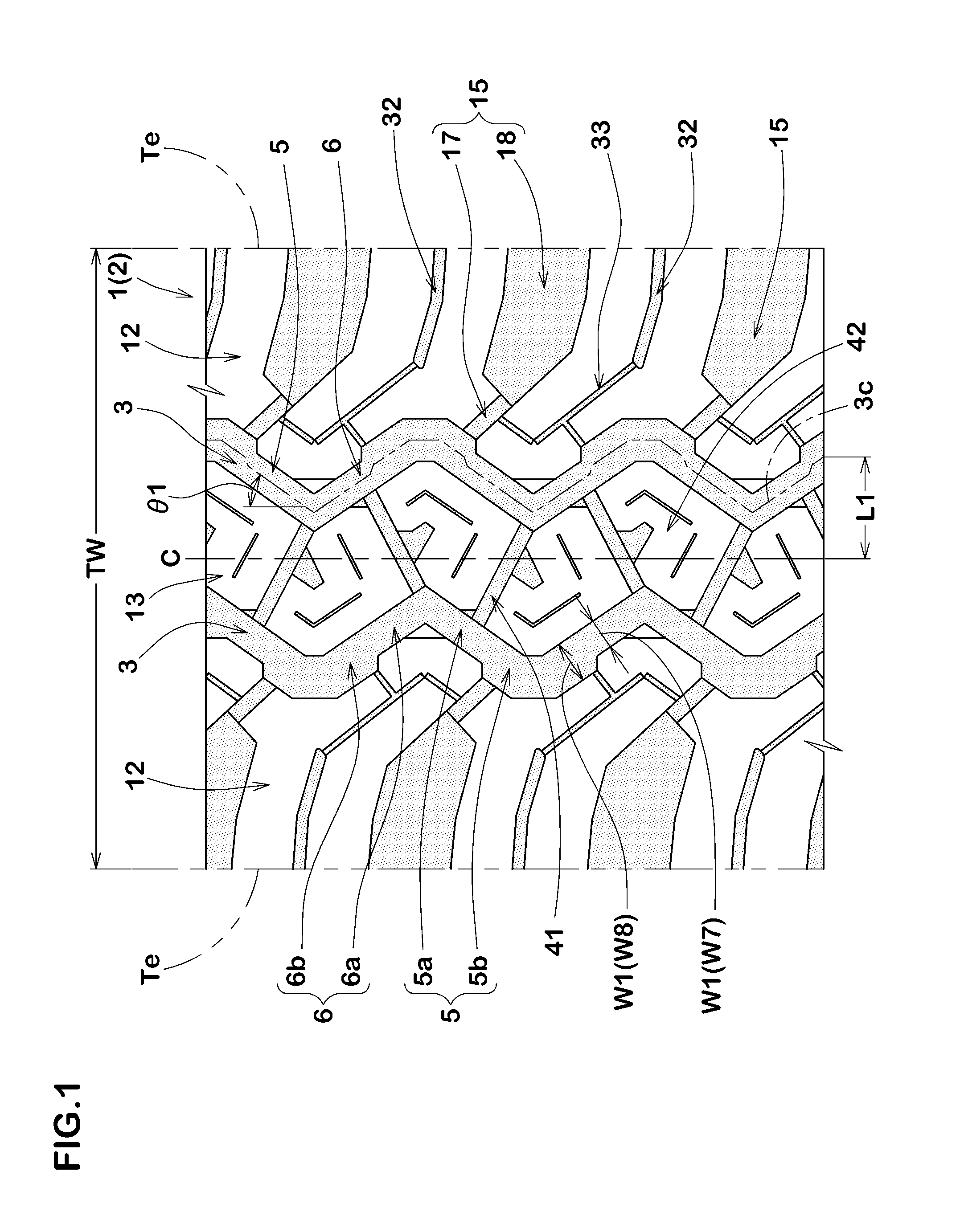
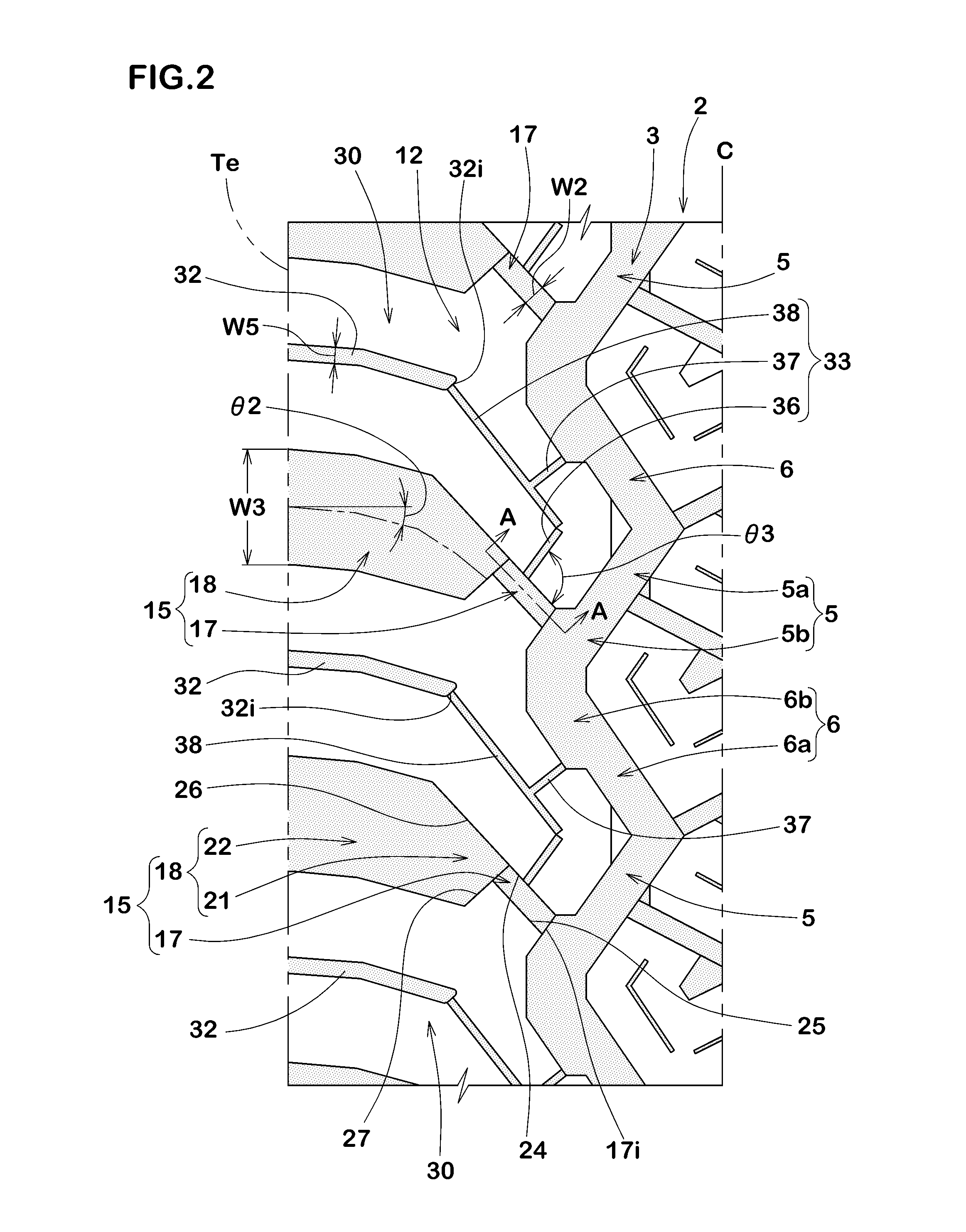
[0007]According to one aspect of the present invention, a pneumatic tire includes a tread portion having a tread edge. The tread portion is provided with a circumferentially extending zigzag shoulder main groove arranged proximate to the tread edge, and a plurality of shoulder lateral grooves each extending axially outwardly from the shoulder main groove. Each of the shoulder lateral grooves includes a first portion and second portion. The first portion has an axially inner end connected to the shoulder main groove and a first groove wall. The second portion is arranged axially outward of the first portion and has a second groove wall. The second portion has a groove width and a groove depth greater than those of the first portion. The first groove wall of the first portion and the second groove wall of the second portion are smoothly continued.

Problems solved by technology

Unfortunately, the tire disclosed by the publication tends to produce a large pumping noise on paved road due to the air passing through the shoulder lateral grooves in a ground contacting patch of the tread.

Method used


Image

  • Pneumatic tire
  • Pneumatic tire
  • Pneumatic tire

Examples


second embodiment

[0093]Pneumatic tires for SUV having a size of 225 / 95R16 and a basic tread pattern shown in FIG. 6 were manufactured based on specifications in Table 2. The tire of Ref 2 listed in Table 2 is configured that the axially inner end faces the second portion with an overlap at the distance L1. The test methods and common specifications of tire or the like are as follows.

Noise Performance Test:

[0094]According to the “Test Procedure for Tire Noise” specified in Japanese JASO C606, the test vehicle as mentioned above was coasted at a speed of 60 km / hr in a straight test course, and the maximum noise sound level dB(A) was measured with a microphone set at 1.2 meter height from the road surface and 7.5 meter sideways from the running centerline in the midpoint of the course. The results were indicated the reciprocal of the sound level using an index, wherein the tire of Ref 2 is being 100. The larger the value, the better the performance is.

Performance in Mud Terrain Test:

[0095]This test was...


PUM


Abstract

A pneumatic tire includes a tread portion provided with a circumferentially extending zigzag shoulder main groove arranged proximate to a tread edge, and a plurality of shoulder lateral grooves each extending axially outwardly from the shoulder main groove. Each of the shoulder lateral grooves includes a first portion and second portion. The first portion includes a first groove wall and an axially inner end connected to the shoulder main groove. The second portion is arranged axially outward of the first portion and includes a second groove wall. The second portion has a groove width and a groove depth greater than those of the first portion. The first groove wall of the first portion and the second groove wall of the second portion are smoothly continued.

Description

BACKGROUND ART[0001]1. Field of the Invention[0002]The present invention is related to a pneumatic tire designed for excellent performance in mud terrain and quiet ride on paved road.[0003]2. Description of the Related Art[0004]Japanese unexamined patent application publication No. 5-278415 discloses an all terrain pneumatic tire that comprises a tread portion provided with a circumferentially extending zigzag main groove and a plurality of broad shoulder lateral grooves extending axially outwardly from the shoulder main groove to form a plurality of shoulder blocks. In mud terrain, the respective shoulder blocks generate traction force by shearing large lump of mud pressed in the shoulder lateral grooves.[0005]Unfortunately, the tire disclosed by the publication tends to produce a large pumping noise on paved road due to the air passing through the shoulder lateral grooves in a ground contacting patch of the tread.SUMMARY OF THE INVENTION[0006]The present invention has been worked ...

Claims


Application Information

Patent Timeline
Patent Type & Authority Applications(United States)
IPC IPC(8): B60C11/03B60C11/13B60C11/12
CPCB60C11/0316B60C11/1204B60C11/13B60C11/1281B60C11/1263B60C2011/0367B60C2011/0346B60C2011/0365B60C2011/0358B60C11/1369B60C2011/1254B60C11/11B60C2011/0388B60C2011/0369B60C2011/0372
Inventor ARAI, HIROSHI
Owner SUMITOMO RUBBER IND LTD
Why Eureka
Try Eureka