Permanent magnet motor

a permanent magnet, magnet technology, applied in the direction of dynamo-electric machines, magnetic circuit rotating parts, magnetic circuit shape/form/construction, etc., can solve the problems of increasing vibration, increasing noise, and high cogging torque, so as to improve the magnetic flux distribution, reduce the reaction flux of armatures, and high efficiency

Active Publication Date: 2006-12-07
TOSHIBA CARRIER CORP
View PDF7 Cites 26 Cited by
  • Summary
  • Abstract
  • Description
  • Claims
  • Application Information

AI Technical Summary

Benefits of technology

[0016] The present invention reduces armature reaction flux, improves magnetic flux distribution in an outer core, and thus provides a highly efficient permanent magnet with reduced noise and vibration.

Problems solved by technology

Consequently, geometric positional relationship between stator and rotor produces high cogging torque, increasing vibration.
Also, voltage induced by stator windings has a harmonic-rich distorted waveform, resulting in not only increased noise, but also increased core loss, which in turn results in reduced efficiency.
Furthermore, if the stator is driven by 3-phase sine wave AC current, only a fundamental wave component contribute effectively to torque while harmonic components produce torque ripple which increases vibration and noise.

Method used


Image

  • Permanent magnet motor
  • Permanent magnet motor
  • Permanent magnet motor

Examples


first embodiment

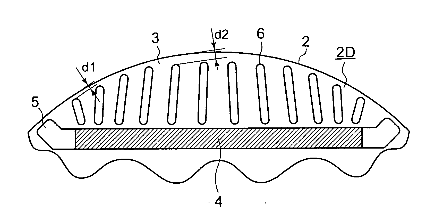
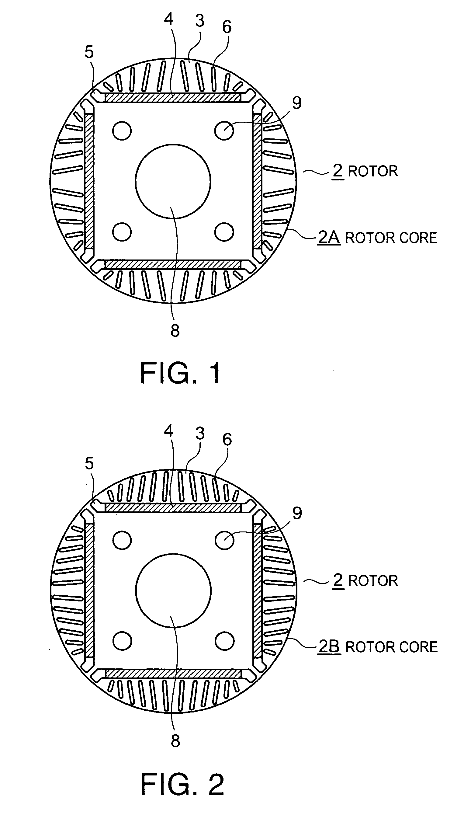
[0029]FIG. 1 is a side view showing an end of a rotor of a permanent magnet motor according to the present invention as viewed along the insertion direction of a rotating shaft before the rotating shaft is inserted. In the figure, the same components as the conventional motor in FIG. 11 are denoted by the same reference numerals as the corresponding components in FIG. 11, and description thereof will be omitted. A rotor 2 consists of a rotor core 2A and a rotating shaft (not shown), where the rotor core 2A is a generally pillar-shaped stack of steel plates cylindrical in outline.

[0030] The rotor core 2A has permanent-magnet-holding slots 5 formed at locations corresponding to sides of an approximately regular quadrangle near the outer circumference of the rotor core 2A. A permanent magnet is buried in each of the permanent-magnet-holding slots 5. A plurality of radially elongated slits 6, for example, ten slits, are arranged apart from each other along each of the permanent-magnet-h...

second embodiment

[0036] Thus, the second embodiment reduces armature reaction flux using the plurality of slits, further improves the magnetic flux distribution in the outer core, and thereby provides a highly efficient permanent magnet with reduced noise and vibration.

third embodiment

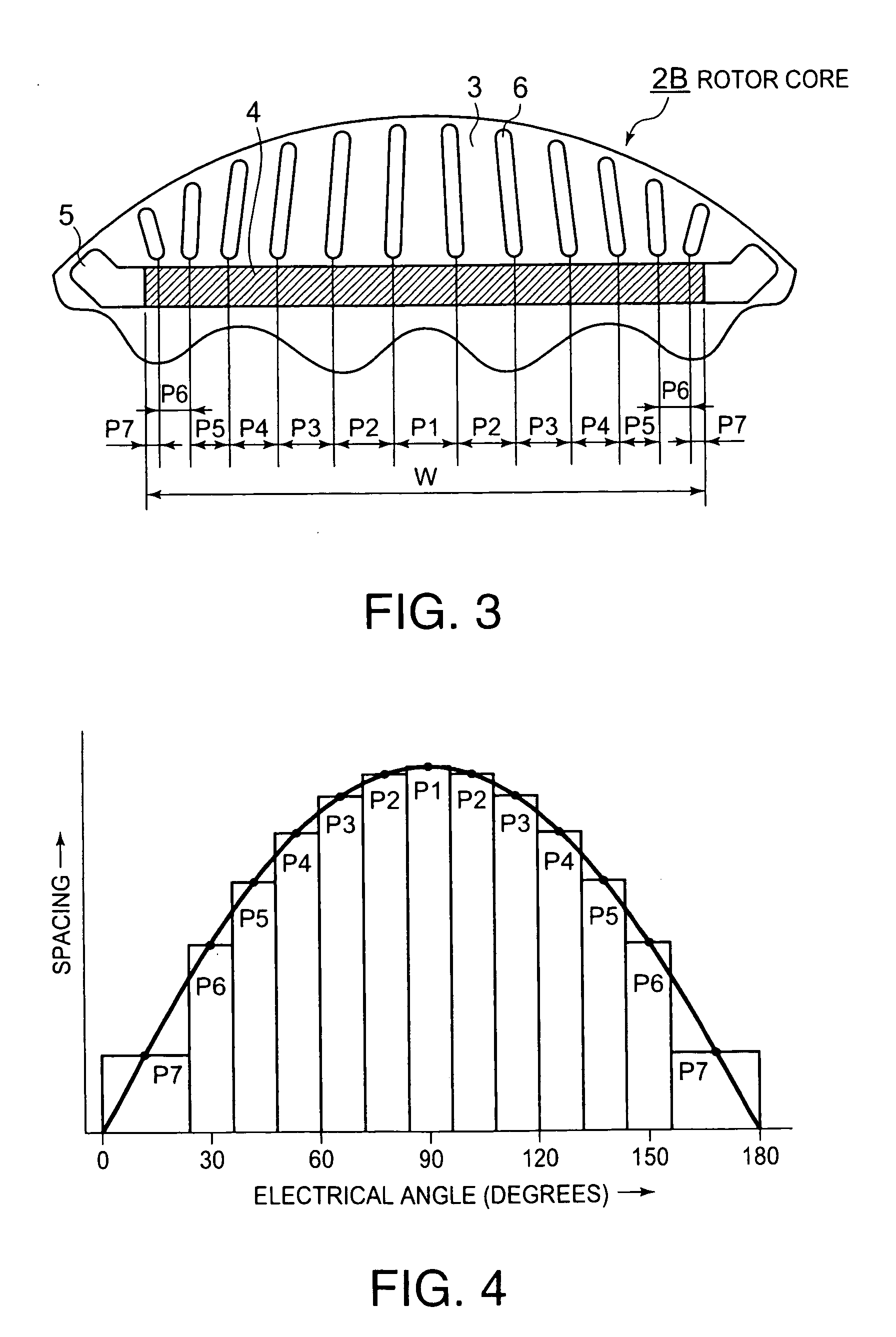
[0037]FIG. 5 is a side view showing an end of a rotor and stator of a permanent magnet motor according to the present invention. In particular, it employs, as the rotor 2, a rotor core 2C similar to the rotor core 2B shown in FIG. 3. The spacings P1 to P7 at the radially inner end of the slits 6 are determined here assuming that the rotor 2 has 2n (=4) magnetic poles while a stator 1 has 3n (=6) teeth each of which has a conductor 7 wound in a concentrated manner, where n is a positive integer (2 in this case) and assuming that sides of the permanent magnets 4, when contracted toward the center, correspond to the base of the sine wave shown in FIG. 4.

[0038] If there is a relationship of 2n:3n between the number of rotor (2) poles and number of stator (1) teeth, angular intervals between the poles of the rotor 2 are smaller than angular intervals between the teeth of the stator 1, and thus the teeth in each phase of the stator 1 cannot receive all the magnetic flux from one pole of t...


PUM


Abstract

To provide a highly efficient permanent magnet motor which can reduce armature reaction flux, improve magnetic flux distribution in an outer core, and thereby reduce noise and vibration.
A permanent magnet motor has permanent-magnet-holding slots 5 formed in those parts of a rotor core 2A which correspond to sides of an approximately regular polygon centered on an axis of the rotor core 2A, permanent magnets 4 inserted in the respective permanent-magnet-holding slots, and four or more radially elongated slits 6 arranged apart from each other along each of the permanent-magnet-holding slots on an outer core outside the permanent-magnet-holding slots, characterized in that at a radially outer end, the slits are spaced approximately equally while at a radially inner end, spacing between the slits is reduced with increasing distance from a center of each permanent magnet, with the spacing at the center being the largest.

Description

BACKGROUND OF THE INVENTION [0001] 1. Field of the Invention [0002] The present invention relates to a permanent magnet motor equipped with a rotor consisting of a plurality of permanent magnets buried in a rotor core. [0003] 2. Related Art [0004] There is disclosed a permanent magnet motor whose demagnetization resistance and efficiency has been improved by burying permanent magnets in a rotor core (see, for example, Japanese Patent Laid-Open No. 11-187597). FIG. 11 is a side view showing an end of a rotor of the permanent magnet motor as viewed along the insertion direction of a rotating shaft of the rotor before the rotating shaft is inserted. In FIG. 11, a rotor 2 consists of a rotor core 2a and rotating shaft (not shown), where the rotor core 2a is a generally pillar-shaped stack of steel plates cylindrical in outline. Near its outer circumference, the rotor core 2a has permanent-magnet-holding slots 5 corresponding to sides of an approximately regular octagon and each of the p...

Claims


Application Information

Patent Timeline
Patent Type & Authority Applications(United States)
IPC IPC(8): H02K1/27H02K1/22H02K3/18H02K21/16
CPCH02K1/276H02K1/246H02K1/2766
Inventor FUTAMI, TOSHIHIKO
Owner TOSHIBA CARRIER CORP
Why Eureka
Try Eureka