Liquid crystal device and electronic apparatus

a liquid crystal display and electronic equipment technology, applied in the direction of identification means, instruments, optics, etc., can solve the problems of unevenness like stains, insufficient control of the tilting direction of the liquid crystal in the reflective display region, and weak alignment control force of the slope, so as to reduce the aperture ratio of the dot region, the effect of reducing the display quality and reducing the alignmen

Active Publication Date: 2006-12-07
BOE TECH GRP CO LTD
View PDF9 Cites 10 Cited by
  • Summary
  • Abstract
  • Description
  • Claims
  • Application Information

AI Technical Summary

Benefits of technology

[0012] An object of the invention is to provide a transflective liquid crystal display device that can prevent display failure, such as an afterimage and unevenness like stains, in both transmissive display and reflective display, and that achieves a bright display with a wide viewing angle.
[0048] An exemplary electronic apparatus of the invention has the above-described liquid crystal display device of the invention. This provides an electronic apparatus having a display section that can perform display in both a transmission mode and a reflection mode, and achieves a high-contrast display with a wide viewing angle in both the modes.

Problems solved by technology

However, this method has two serious problems.
One problem is a weak alignment control force of the slope in the multigap.
The other problem is that the tilting direction of liquid crystal in the reflective display region is not controlled sufficiently.
Disorderly tilting of the liquid crystal causes disclination on the boundary between different liquid crystal alignment regions, which results in an afterimage and the like.
Moreover, since the liquid crystal alignment regions have different viewing-angle characteristics, when the liquid crystal display device is viewed from an oblique direction, unevenness like stains appears.

Method used


Image

  • Liquid crystal device and electronic apparatus
  • Liquid crystal device and electronic apparatus
  • Liquid crystal device and electronic apparatus

Examples


first embodiment

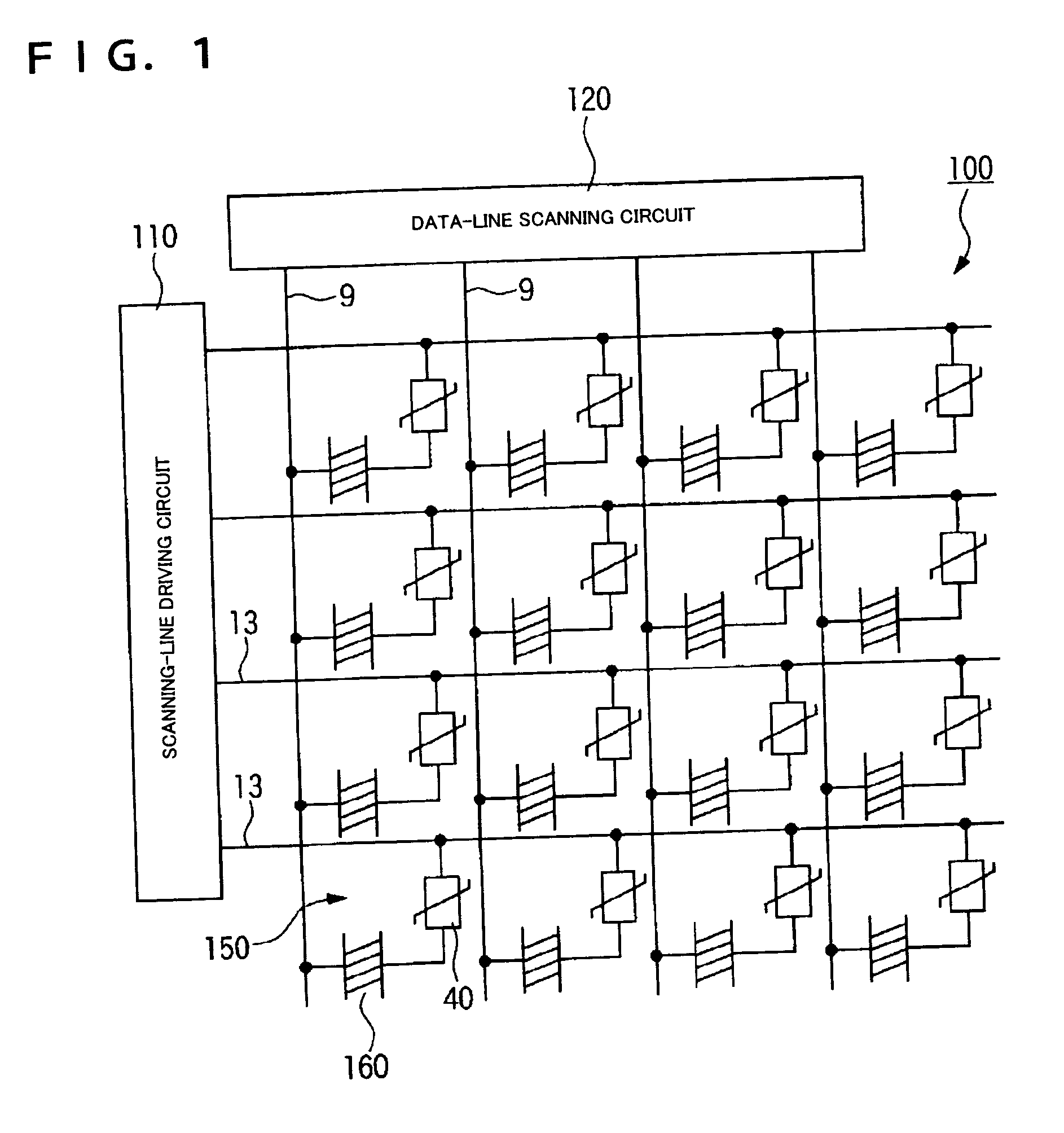
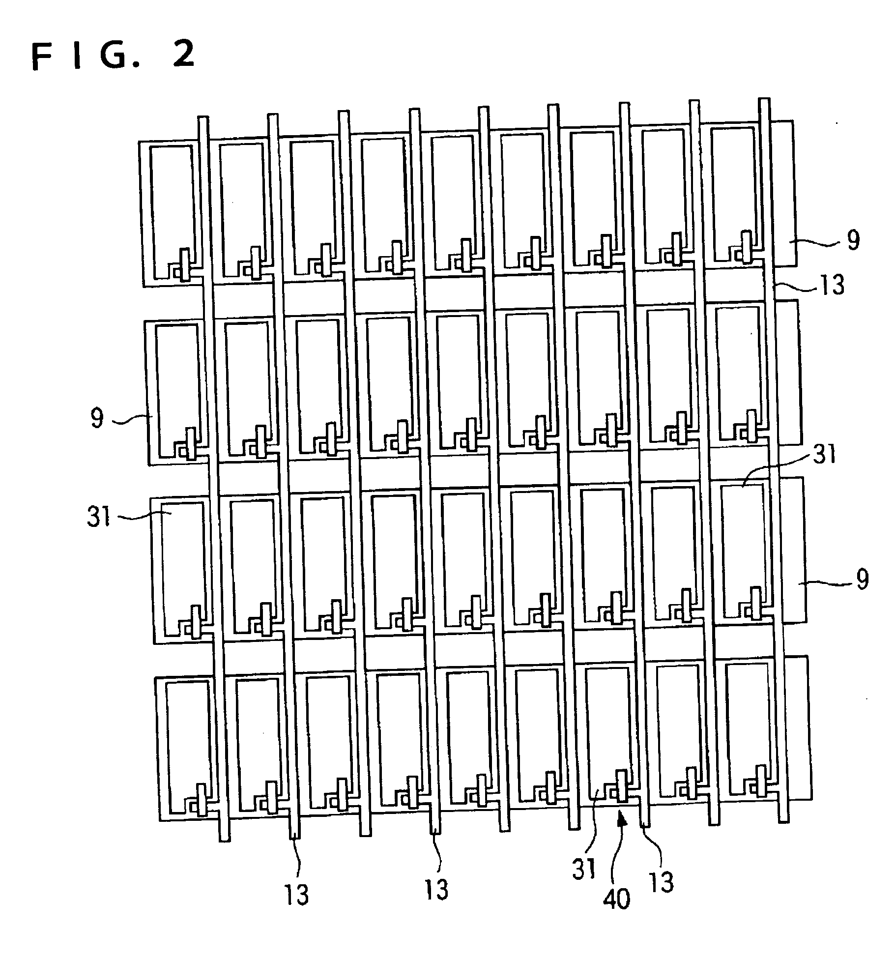
[0062]FIG. 1 is an exemplary circuit diagram of a liquid crystal display device according to the invention, FIG. 2 is a structural plan view of one pixel region in the liquid crystal display device, and FIGS. 3(a) and 3(b) are an enlarged structural plan view and a structural sectional view, respectively, of the pixel region. A liquid crystal display device shown in these figures is an active-matrix color liquid crystal display device using TFDs (thin film diodes) (two-terminal nonlinear elements) as switching elements. The liquid crystal display device of this embodiment can include a liquid crystal layer made of a liquid crystal having a negative dielectric anisotropy that is initially aligned in the vertical direction.

[0063] As shown in FIG. 1, a liquid crystal display device 100 of this exemplary embodiment includes a scanning-signal driving circuit 110 and a data-signal driving circuit 120. The liquid crystal display device 100 also can include signal lines, that is, a pluralit...

fourth embodiment

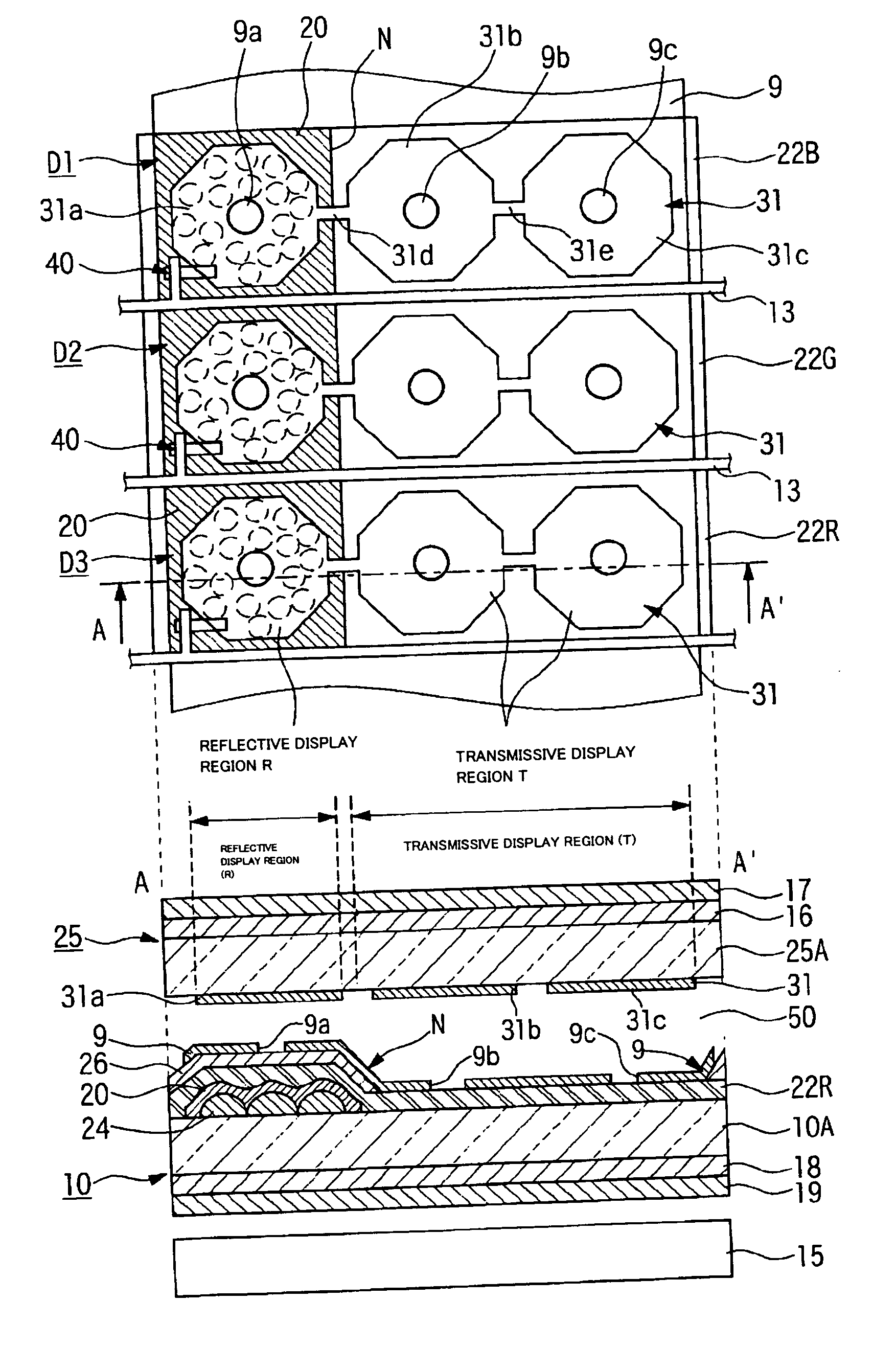
[0128] As described in the fourth embodiment, the liquid crystal display device of the invention has a multigap structure, and the thickness of a liquid crystal layer 50 in the reflective display region R is smaller than in the transmissive display region T. Therefore, an alignment control force of an oblique electric field for the liquid crystal in the reflective display region R is stronger than in the transmissive display region T. As long as the apertures provided in the common electrode 9 have the same size, the aperture in the reflective display region R have an alignment control force stronger than at the apertures 9b and 9c in the transmissive display region T. Accordingly, in this embodiment, the apertures 19a smaller than the apertures 9b and 9c in the transmissive display region T are provided in the reflective display region R, thereby increasing the aperture ratio of the reflective display region R and achieving a bright reflective display while ensuring an alignment co...


PUM

PropertyMeasurementUnit
thicknessaaaaaaaaaa
thicknessaaaaaaaaaa
diameteraaaaaaaaaa

Abstract

Aspects of the invention provide a transflective liquid crystal display device that prevents display failure, such as an afterimage and unevenness like stains, and achieves a bright display with a wide viewing angle in both transmissive display and reflective display. The liquid crystal display device of the invention is a vertically-aligned transflective liquid crystal display device having a multigap structure. Each pixel can include, in a dot region, a plurality of islands, and connecting portions for electrically connecting the adjoining islands. Two islands, of the islands, can be disposed in a transmissive display region, and the remaining island is disposed in a reflective display region. A boundary sloping area in which the thickness of a liquid crystal layer continuously changes is disposed right below the connecting portion in the pixel electrode.

Description

[0001] This is a Continuation of application Ser. No. 10 / 889,250 filed Jul. 13, 2004. This application claims the benefit of Japanese Patent Application No. 2003-282775, filed Jul. 30, 2003. The entire disclosures of the prior applications are hereby incorporated by reference herein in their entirety.BACKGROUND OF THE INVENTION [0002] 1. Field of Invention [0003] The present invention relates to a liquid crystal display device and an electronic apparatus. [0004] 2. Description of Related Art [0005] Some related art transflective liquid crystal display devices utilize external light in bright places, in a manner similar to that in reflective liquid crystal display devices, and make the display visible with a backlight in dark places, in a manner similar to that in transmissive liquid crystal display devices. Such related art transflective liquid crystal display devices include a liquid crystal layer disposed between an upper substrate and a lower substrate, and a reflective film form...

Claims


Application Information

Patent Timeline
Patent Type & Authority Applications(United States)
IPC IPC(8): G02F1/1335G02B5/20G02F1/1337G02F1/1365G02F1/139G09F9/30G09F9/35
CPCG02F1/133371G02F1/133553G02F1/133555G02F1/133707G02F2001/134345G02F1/136227G02F1/1365G02F1/1393G02F1/133753G02F1/134345G02F1/1335
Inventor OKUMURA, OSAMU
Owner BOE TECH GRP CO LTD
Why Eureka
Try Eureka