Eureka AIR delivers breakthrough ideas for toughest innovation challenges, trusted by R&D personnel around the world.

Electronic apparatus with thermal module

Active Publication Date: 2006-12-07
VIA TECH INC
View PDF2 Cites 4 Cited by
  • Summary
  • Abstract
  • Description
  • Claims
  • Application Information

AI Technical Summary

Benefits of technology

[0009] In view of the foregoing, the present invention is to provide an electronic apparatus with a thermal transmitting module applied to a package for thermal dissipation. The package is disposed on a circuit board and includes a surface facing to the circuit board. At least one heat source and a plurality of electric terminals are disposed on the surface to electrically connect with the circuit board. The present invention provides an effective thermal transmitting path, which enhancing the thermal dissipating efficiency and improving the reliability of the electronic apparatus.
[0015] As mentioned above, by disposing a thermal transmitting module with an electronic apparatus according to the present invention may provide an effective thermal transmitting path, which enhancing the thermal dissipating efficiency and improving the reliability of the electronic apparatus.

Problems solved by technology

The heat dissipation has become an essential issue in order to maintain a normal operation.
The package 110 is thus not performed an effective thermal dissipation and which leads to the raise of the operation temperature and the degradation of the efficiency and reliability of the electronic apparatus 100.
Because the heat sources of the package of MPM between the package and the circuit board has no effective thermal transmitting path, which leads to the operation temperature of the electronic apparatus is too high to be normally operated.

Method used


Image

  • Electronic apparatus with thermal module
  • Electronic apparatus with thermal module
  • Electronic apparatus with thermal module

Examples


Embodiment Construction

[0024] The present invention will be apparent from the following detailed description, which proceeds with reference to the accompanying drawings, wherein the same references relate to the same elements.

[0025] The present invention provides a thermal transmitting path to an electronic apparatus. The electronic apparatus includes a package disposed over a circuit board. The package has a surface facing to the circuit board and the surface has at least one heat source.

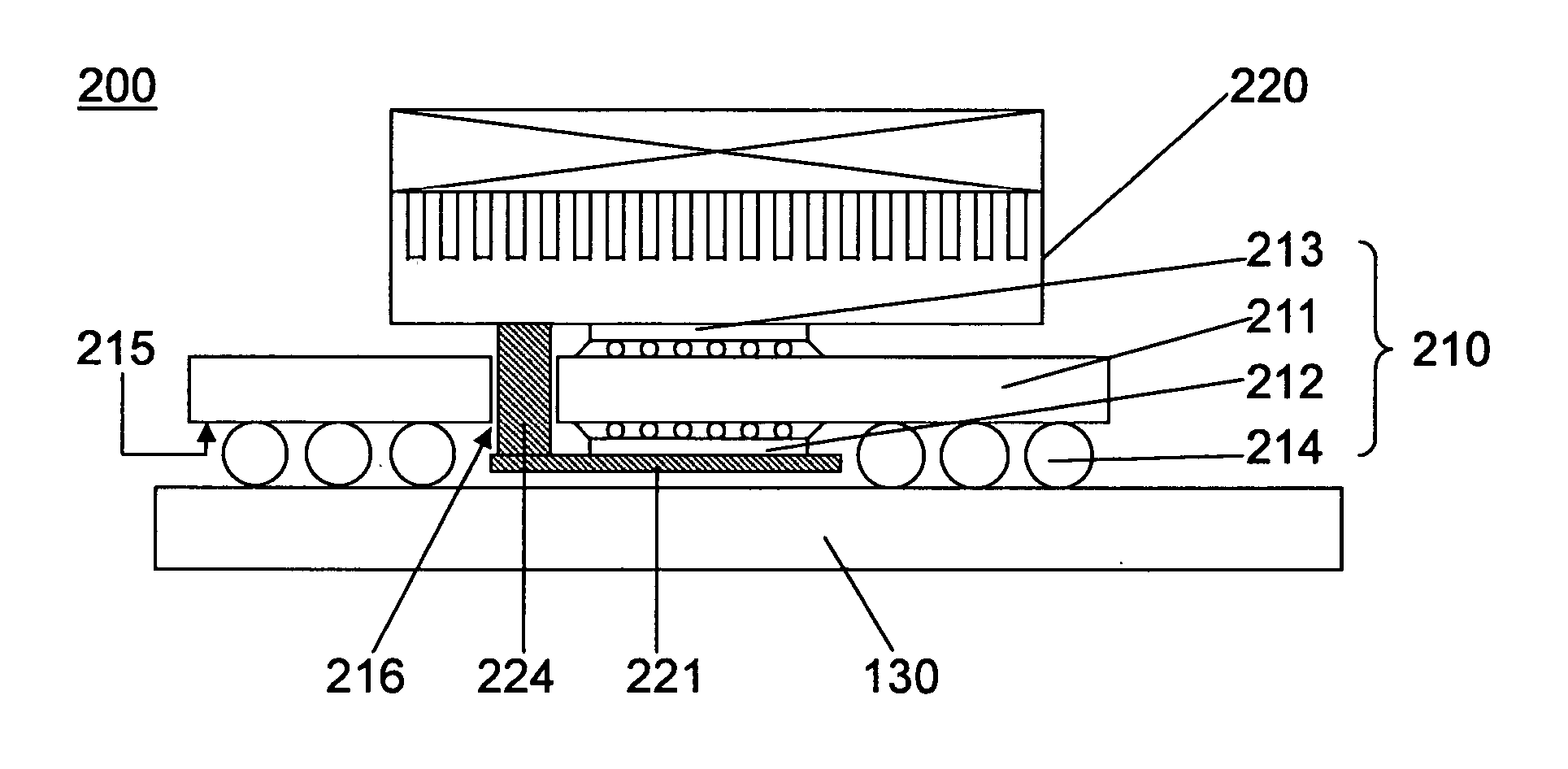
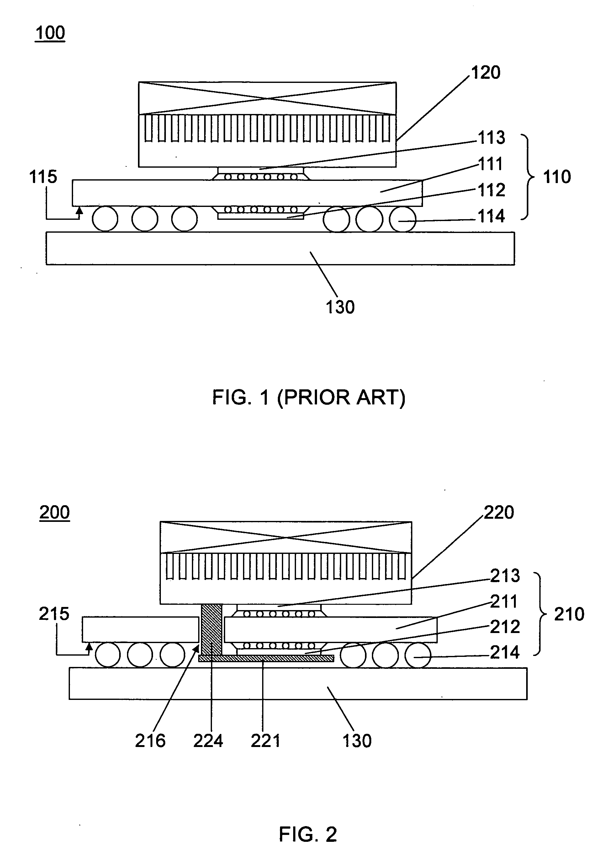
[0026]FIG. 2 shows a cross-sectional view of a first preferred embodiment of an electronic apparatus 200 according to the present invention. A package 210 of stacked MPM includes a substrate 211, a first chip 212, a second chip 213 and a plurality of electric terminals 214. The first chip 212 and the second chip 213 are respectively electrically connected to the corresponding surfaces of the substrate 211 by a flip-chip packaging technology.

[0027] The package 210 is electrically connected with the circuit board 130 th...


PUM


Abstract

An electronic apparatus includes a package, a circuit board, a thermal dissipating module and a thermal transmitting module. The package includes a substrate, a heat source and a plurality of electric terminals electrically connected to the circuit board. The heat source and the electric terminals are disposed on a surface of the substrate facing to the circuit board. The heat source is located between the substrate and the circuit board. The thermal transmitting module passes through the electric connection structures between the package and the circuit board and connects the heat source of the package with the thermal dissipating module. Thus, the thermal transmitting module enhances the thermal dissipating efficiency for the heat source of the package and improves the reliability of the electronic apparatus.

Description

BACKGROUND OF THE INVENTION [0001] 1. Field of Invention [0002] The present invention relates to an electronic apparatus, and more particularly, to an electronic apparatus with a thermal transmitting module. [0003] 2. Related Art [0004] Accompanying to the development of semiconductor device and process, more and more functionalities are integrated within the same scale size. That is, more heats are dissipated from the same area. The heat dissipation has become an essential issue in order to maintain a normal operation. In addition, multiple chips trend to be packaged as a multiple packaging module (MPM), and much more heats are dissipated from the package within the same area. An excellent packaging structure for the electronic apparatus is thus important to provide an effective thermal dissipating efficiency. [0005]FIG. 1 shows a cross-sectional view of a conventional electronic apparatus. An electronic apparatus 100 includes a package 110 of stacked MPM electrically connected to ...

Claims


Application Information

Patent Timeline
IPC IPC(8): G06F1/20
CPCG06F1/20H01L23/367H01L23/467H01L23/49833H01L25/0657H01L2224/16H05K2201/10734H01L2225/06589H01L2924/15311H05K1/0204H05K1/141H05K3/3436H05K2201/066H01L2225/06517H01L2924/00011H01L2924/00014H01L2224/0401
Inventor YANG, CHIH-ANLIN, CHUNG-AN
Owner VIA TECH INC
Why Eureka
Eureka Blog
Learn More