Bar with sliding handgrips for resistance exercise devices

a resistance exercise and bar technology, applied in the direction of weights, frictional force resistors, gymnastics, etc., can solve the problems of high profile, unfavorable use of oval bars, and unbalance of dibrowski devices, so as to reduce joint stress and strain, increase range of motion, and exercise more muscle fibers

Inactive Publication Date: 2006-12-07
WILSON JEFFREY DALE +2
View PDF7 Cites 31 Cited by
  • Summary
  • Abstract
  • Description
  • Claims
  • Application Information

AI Technical Summary

Benefits of technology

[0013] The various embodiments of the invention provide advantages over traditional exercise devices. Since the hands (or legs) are not constrained to fixed paths of motion during exercise movements, more natural exercise movements are possible with the bar of the present invention resulting in reduced joint stress and strain. The sliding handgrips (or footgrips) also provide an increased range of motion during exercise movements thereby exercising more muscle fibers as compared to traditional exercises. New, heretofor unavailable exercise movements and variations are also made possible by the bar of the present invention. Adding variation to routine exercise movements has been proven to stimulate muscle growth. Since the handgrips (or footgrips) remain equidistant from the center of gravity, symmetrical loading of the left and right sides is always maintained during exercise movements. Finally, the ability of the handgrips (or footgrips) on the invention to slide during exercise movements leads to maximum muscle fiber recruitment since additional muscles are needed to stabilize and control a given motion during the exercise movements.

Problems solved by technology

A disadvantage of the Brasher device is that the oval bar employed to mount the cable-supporting pulleys upon has a high profile and does not have the familiar appearance and feel of a conventional (stationary handgrips) barbell wherein the bar is not oval but substantially cylindrical.
Accordingly, due to the compressibility and extensibility of the springs, the Dibrowski device may become unbalanced when the handgrips are not equidistant from the center of gravity of the weighted bar as, for example, when the bar is tilted.
This, in turn, shifts more weight over the more fatigued or weaker arm, causing it to drop further and with weight shifted off of the stronger arm, it will rise faster causing a rapidly increasing tilt in the bar.
The result is that the Troutman bar can quickly slide to one side causing the lower arm to collapse, cause muscle strain, or even cause the exerciser to fall off of the bench.
The relative angle of rotation of the handgrips with respect to one another is not synchronized which is undesirable for some exercises.
The handgrip linking means (cables) are not disposed to abut the weight bar and, accordingly, the structure has an awkward, relatively high profile.
Further, the weight bar is not adapted to be free-standing and is adapted for use only with the other structural features of the machine.

Method used


Image

  • Bar with sliding handgrips for resistance exercise devices
  • Bar with sliding handgrips for resistance exercise devices
  • Bar with sliding handgrips for resistance exercise devices

Examples


Embodiment Construction

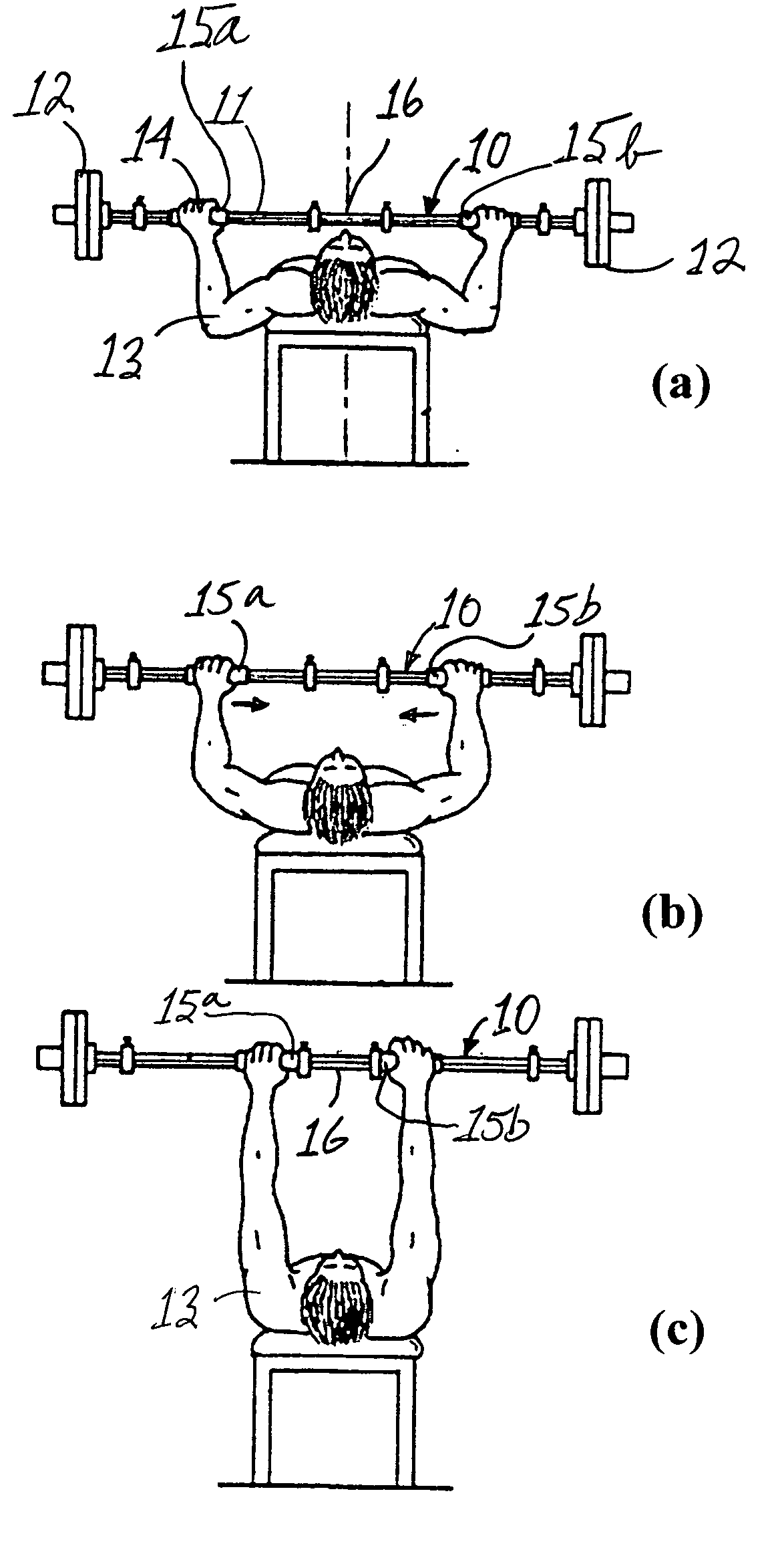
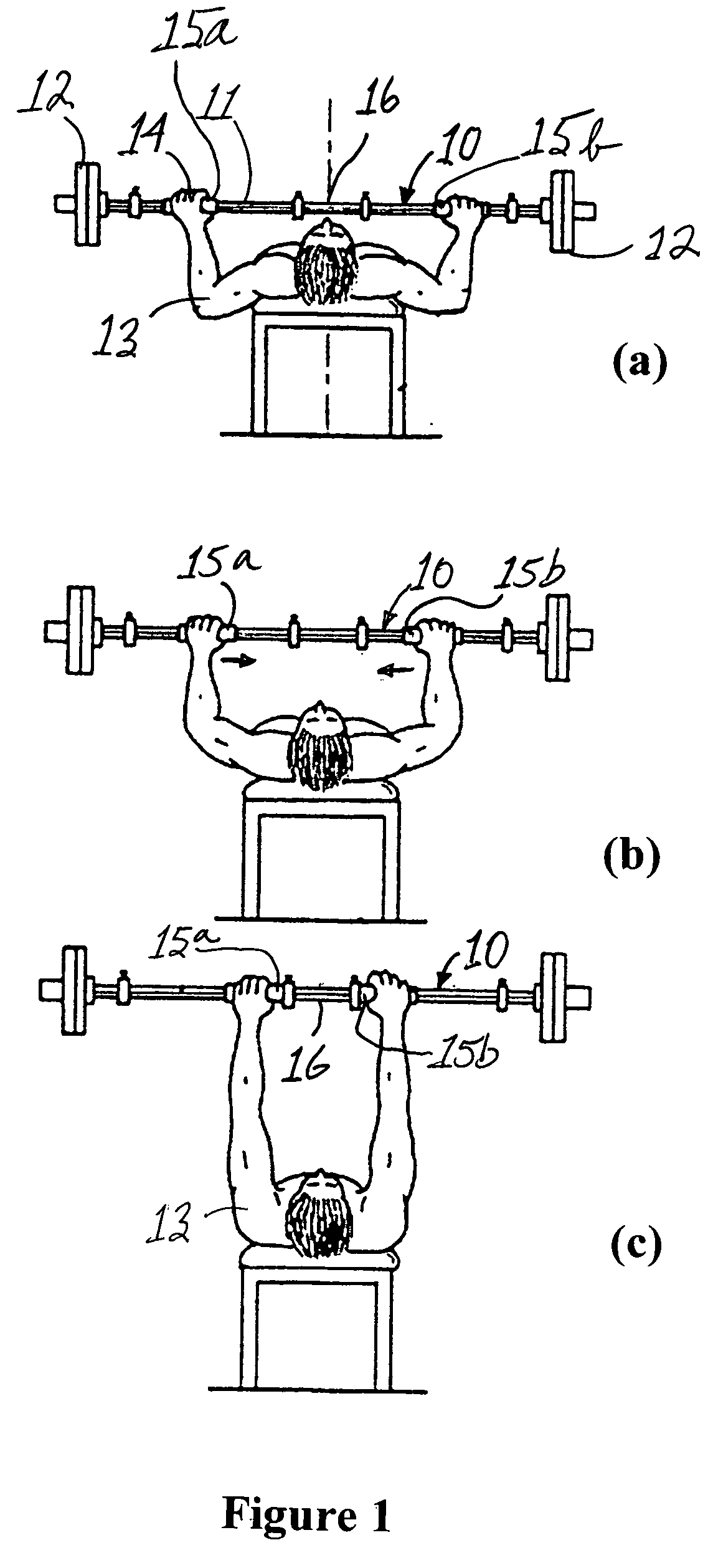
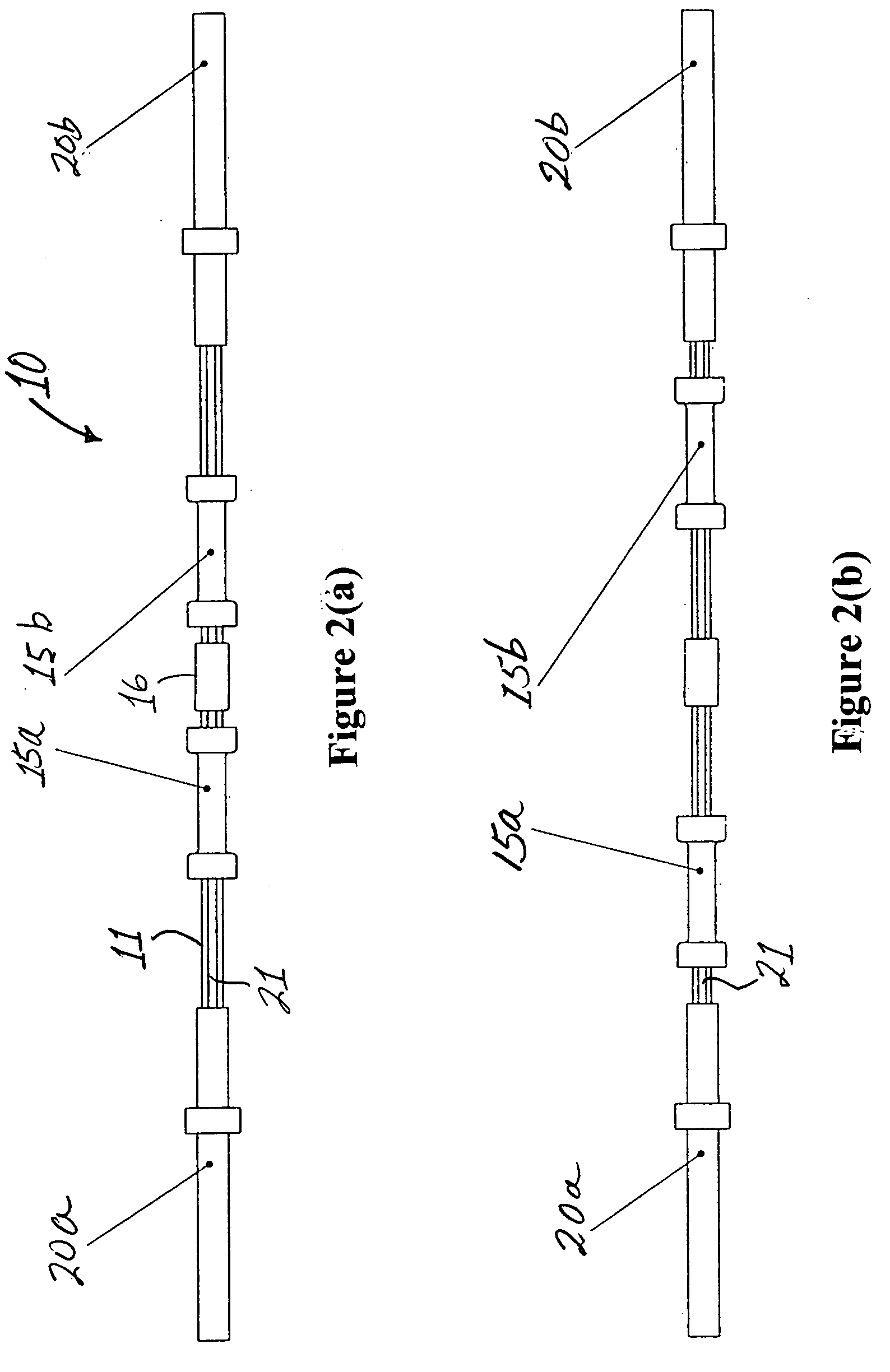
[0052] The present invention provides an exercise apparatus for performing two-handed exercises and includes a bar to which a resistive force is applied and a pair of handgrip assemblies concentrically and slidably attached to the bar which the user grips in order to move the bar against the resistive force during the performance of an exercise. The resistive force may be simply the weight of the bar or it may comprise weights connected to the bar. Alternatively, another piece of equipment capable of providing a resistive force can be connected to the bar by resistive force attachment means such as, for example, by a cable or two “U”bolts. Each handgrip is slidably connected to the bar, the sliding paths being generally parallel to the long axis of the bar, generally in line with each other, and disposed symmetrically with respect to a center plane perpendicular to the long axis of the bar and intersecting the bar at the center of gravity thereof. (The terms “generally parallel” and...


PUM


Abstract

An elongate bar having sliding handgrips concentrically mounted thereon adapted for use with various types of resistance-type exercise devices. In a preferred embodiment, the handgrips, which are constrained to move only in an axial direction with respect to the bar, are interconnected on an inner bar-facing portion of the handgrips by linking means such as belts, in such a manner that the handgrips and bar retain a low profile, and the handgrips remain equidistant from the center of the bar throughout their axial range of motion. In the preferred embodiment, the linking means are belts that are supported by pulleys housed within recesses in the bar and rotatably attached thereto. Embodiments of the bar for performing various exercises are disclosed which include resistive force attachment means affixed to the bar operable for attaching weights, lever arms, springs, cable(s), belts(s), elastic bands or the like thereto or by using an exerciser's own body weight to provide a resistive force for exercising a variety of muscles.

Description

REFERENCE TO RELATED APPLICATIONS [0001] The present application is a continuation-in-part of copending U.S. patent application Ser. No. 10 / 691,733, filed Oct. 22, 2003, which has been allowed.BACKGROUND OF THE INVENTION [0002] 1. Field of the Invention [0003] The present invention relates to a resistance exercise device and, more particularly, to a bar having a pair of handgrips slidably mounted thereon, the bar being adapted to be attached to a resistive force such as weights. [0004] 2. Prior Art [0005] Resistance exercise devices are well represented in the art. Perhaps the most common such device is the barbell in which weights are removably attached to opposing ends of an elongate bar. An exerciser grips the bar with both hands and moves the bar and weights through a range of motion against the force of gravity. In most such barbell devices, the handgrips are a knurled or textured portion on the outer surface of the bar and necessarily remain stationary with respect to the bar ...

Claims


Application Information

Patent Timeline
Patent Type & Authority Applications(United States)
IPC IPC(8): A63B21/072A63B21/075A63B21/015A63B23/12
CPCA63B21/015A63B21/072A63B23/1254A63B21/1469A63B21/1434A63B21/4035A63B21/4017
Inventor WILSON, JEFFREY DALEJENNEVE, JEFFSANCHEZ, DANIEL STEVEN
Owner WILSON JEFFREY DALE
Why Eureka
Try Eureka