Thermo roll

a roll and thermoplastic technology, applied in the direction of shafts, bearings, calenders, etc., can solve the problems of limited heat transfer capacity of steel rolls heated with oil, high oil temperature at high operating capacities, and complex roll structure, etc., to reduce the overall thermal conductivity of the roll and reduce the overall thermal conductivity. , the effect of lowering the thermal conductivity

Inactive Publication Date: 2006-12-07
VALMET TECH INC
View PDF12 Cites 15 Cited by
  • Summary
  • Abstract
  • Description
  • Claims
  • Application Information

AI Technical Summary

Benefits of technology

[0023] In accordance with another aspect of another embodiment of the present invention, an aim is to provide a novel roll shell to make the technical structure of the roll less complex and to improve the heat transfer properties of the roll.
[0223] A general object of the present invention is to reduce the weaknesses associated with the prior art and to provide a thermo roll with improved heat transfer properties and to provide a method using the thermo roll, by means of which thermo roll and method it is possible to manufacture low-gloss and smooth printing papers and board products advantageously and efficiently.

Problems solved by technology

The heat transfer capacity of steel rolls heated with oil is limited in practice by the availability of hot oil, the temperature of which is today about 300° C.
The prior art is characterized in that the roll or the load-bearing base of the roll is composed of steel or equivalent, whose heat transfer properties are not the best possible (typically, the thermal conductivity of the material λ that in order to improve the heat transfer properties of the roll, the shell of the roll is provided with a material layer that conducts heat well and / or with heat transfer passages, so that the structure of the roll is technically complex and, thus, expensive, and that the heat transfer passages are situated in the roll shell at a distance of about 40-80 mm from the outer surface, so that with the materials used today a great temperature difference (ΔT) is created in the roll shell, which leads to a high oil temperature at high operating capacities.

Method used


Image

  • Thermo roll
  • Thermo roll
  • Thermo roll

Examples


first embodiment

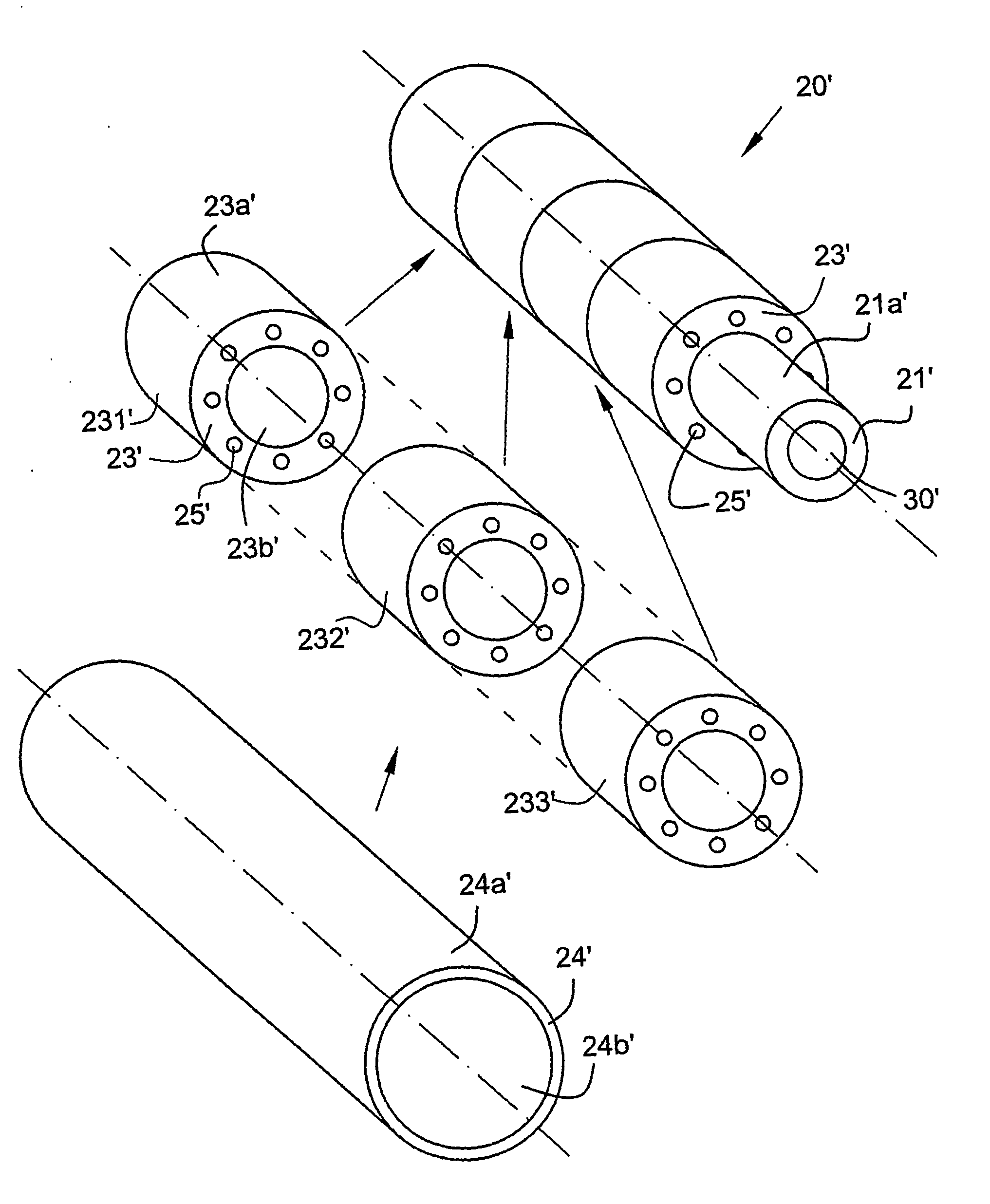
[0304] In accordance with the invention, at least two different material layers 11′, 13′, 14′, 21′, 23′, 24′ are arranged, using a manufacturing technique, radially one within the other in the shell of the thermo roll, which material layers have been manufactured with respect to their manufacturing technique in different stages or by different methods, so that in accordance with one embodiment the thermal conductivity of each material layer in the shell of the thermo roll is in a range of 20-70 W / mK.

second embodiment

[0305] In accordance with the invention, material layers 11′, 13′, 14′, 21′, 23′, 24′ are arranged radially one within the other in the shell of the thermo roll, the thermal conductivities of at least two material layers being different from one another, so that in accordance with one embodiment at least one of said material layers, the thermal conductivities of which are different from one another, is a heat transfer layer 13′, 23′, which is of a metal material that conducts heat particularly well, the effective thermal conductivity λ of the thermo roll across the shell of the thermo roll being >70 W / mK.

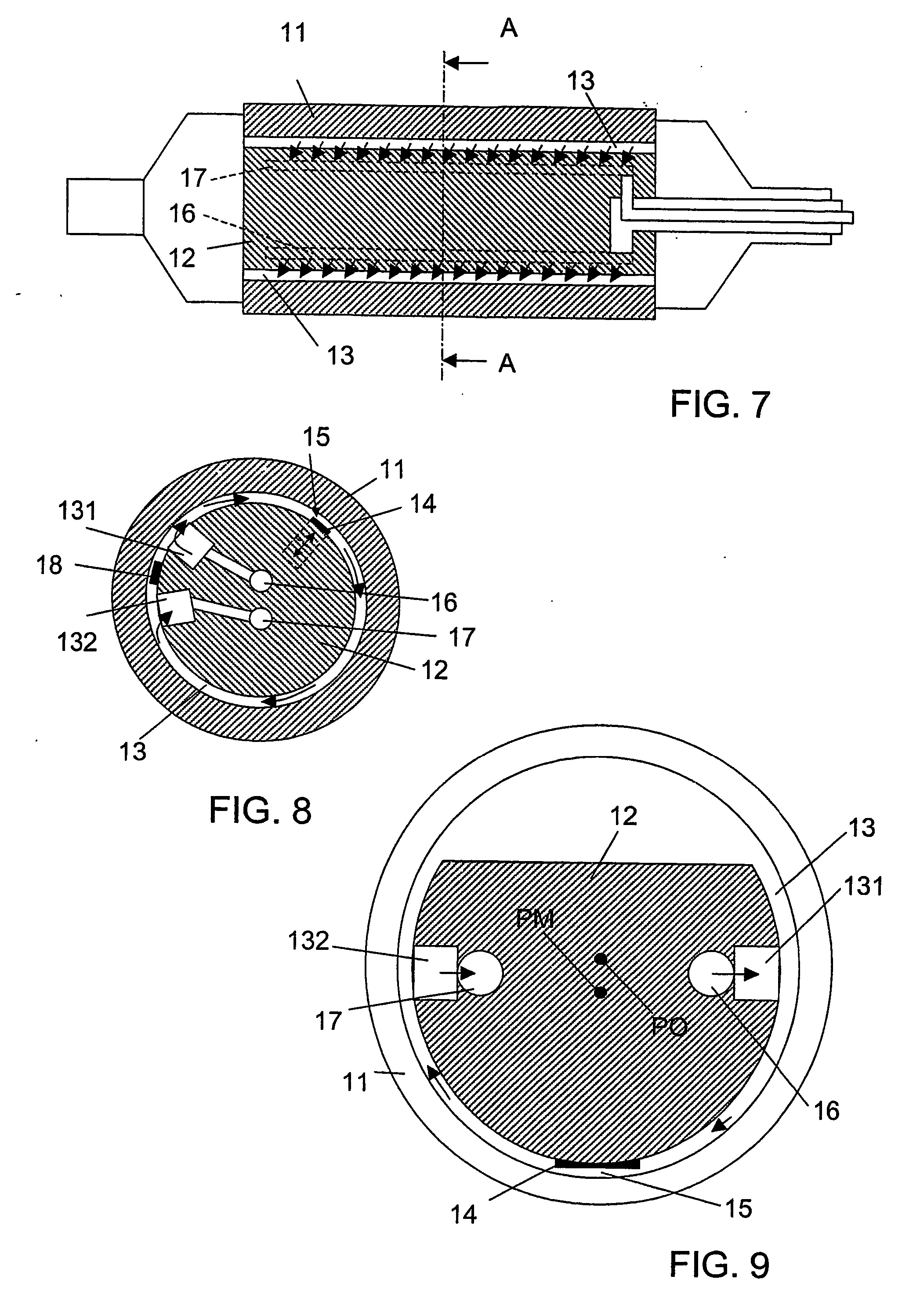
[0306] In addition, there are heat transfer medium flow passages 15′, 25′, 30′, 151′, 152′ in at least one material layer 11′, 13′, 14′, 21′, 23′, 24′ or in a material layer 11′, 13′, 14′, 21′, 23′, 24′ manufactured in stages or in layers or assembled in stages or in layers or confined by at least one material layer inside itself or in a boundary zone of two material layers.

[0307] ...

third embodiment

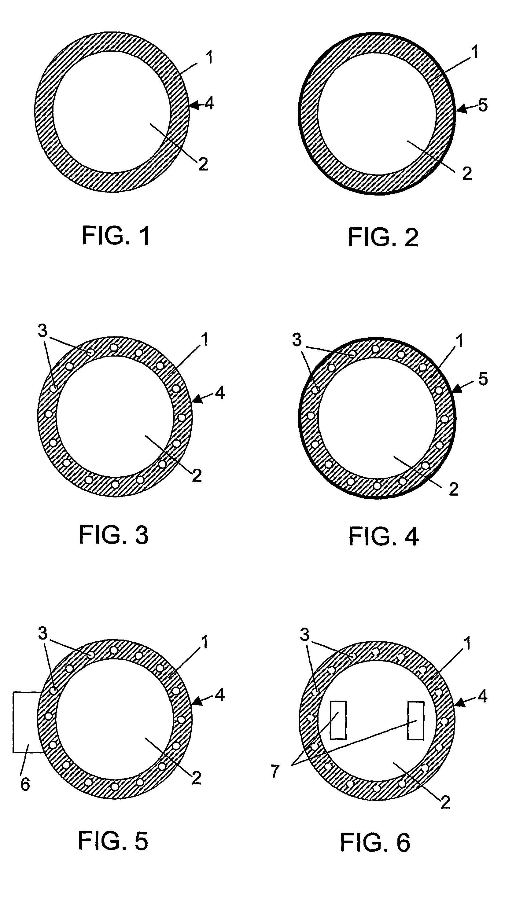
[0341]FIG. 15 shows the shell of a thermo roll 101′ in accordance with the invention. The shell of the thermo roll 101′ of FIG. 15 comprises two material layers whose thermal conductivity changes in a layer by layer fashion in the radial direction of the thermo roll 101′. A material layer that conducts heat better is arranged to form one heat transfer means of the thermo roll 101′, said material layer forming a heat transfer layer 13′, which in FIG. 15 is on the inner side of a thermally less conductive surface layer 14′.

[0342] The thermo roll 101′ shown in FIG. 15 can be heatable from inside, so that the inner surface 13b′ of the inner heat transfer layer 13′ defines within itself a center passage 30′ as a second heat transfer means of the thermo roll 101′, a heat transfer medium flowing in said center passage, or the center passage 30′ is provided with a third heat transfer means, such as an internal induction heating coil in a Tokuden roll, or the thermo roll 101′ can also be pro...


PUM


Abstract

A heatable and / or coolable roll, i.e. a thermo roll, of a fibrous web machine for the treatment of a fibrous web, is, for example, for pressing and / or calendering the fibrous web in contact, i.e. in a nip, between the thermo roll and a backing member which is in contact with the thermo roll or for drying or cooling the fibrous web on the shell surface of the thermo roll. A semi-finished product of a thermo roll is manufactured using a thermo roll.

Description

CROSS REFERENCES TO RELATED APPLICATIONS [0001] This application is a U.S. national stage application of International App. No. PCT / FI2004 / 000503, filed Aug. 30, 2004, and claims priority on FI App. No. 20031230, filed Sep. 1, 2003; FI App. No. 20031232, filed Sep. 1, 2003; FI App. No. 20031231; filed Sep. 1, 2003, FI App. No. 20031233; filed Sep. 1, 2003; and FI App. No. 20031743, filed Nov. 28, 2003, the disclosures of which are incorporated by reference herein. STATEMENT AS TO RIGHTS TO INVENTIONS MADE UNDER FEDERALLY SPONSORED RESEARCH AND DEVELOPMENT [0002] Not applicable. BACKGROUND OF THE INVENTION [0003] The present invention relates to fibrous web machines, advantageously to apparatus for the treatment of a paper, board, pulp or equivalent web, such as paper, board or pulp machines and finishing devices associated with them, such as calenders. [0004] The present invention relates to a heatable and / or coolable roll, i.e. a thermo roll, of a fibrous web machine for the treatm...

Claims


Application Information

Patent Timeline
Patent Type & Authority Applications(United States)
IPC IPC(8): F16C13/00D21G1/02
CPCD21G1/02D21G1/028D21G1/0266
Inventor PIETIKAINEN, REIJOSAARIKOSKI, TEEMUKORHONEN, MIKATERVONEN, MATTITORVI, TIMOLIIMATAINEN, JARISALMINEN, KARISUOMI, EEROLAAKSO, MARI
Owner VALMET TECH INC
Why Eureka
Try Eureka