
Battery powered surgical instrument

a surgical instrument and battery technology, applied can solve the problem that the force of the surgical stapling device is limited and should be required in the field of surgical instruments

Active Publication Date: 2006-12-14
TYCO HEALTHCARE GRP LP
View PDF99 Cites 789 Cited by
  • Summary
  • Abstract
  • Description
  • Claims
  • Application Information

AI Technical Summary

Benefits of technology

[0014] In another embodiment, the stapler has a power supply that can actuate the stapler and the power source can easily move the drive mechanism to an appropriate position for the next stapling operation.
[0015] According to another aspect of the present disclosure, there is provided a surgical stapler. The stapler has a handle assembly including a trigger and a clamping device including a staple cartridge with a plurality of staples and an anvil having a fastener forming surface thereon. The stapler also has a controller configured to determine an occurrence of clamping by the anvil and the staple cartridge. The controller controls firing of the plurality of staples from the staple cartridge. When the trigger is actuated the controller delays firing of the plurality of staples from the staple cartridge to provide for a predetermined time period of tissue compression of the tissue between the anvil and staple cartridge. The controller outputs a control signal to allow firing once the predetermined time period is reached. The stapler also has a motor having a geared assembly. The motor is disposed in the handle and configured to receive the control signal from the controller. The motor is operatively connected to the staple cartridge to fire the staples from the staple cartridge once the control signal is received.

Problems solved by technology

Also, once compression of the desired stapling location is made, only a very limited degree of force to the surgical stapling device should be required in order to complete the actuation of the device and thus firing of the staples such as by actuating a trigger switch.

Method used


Image

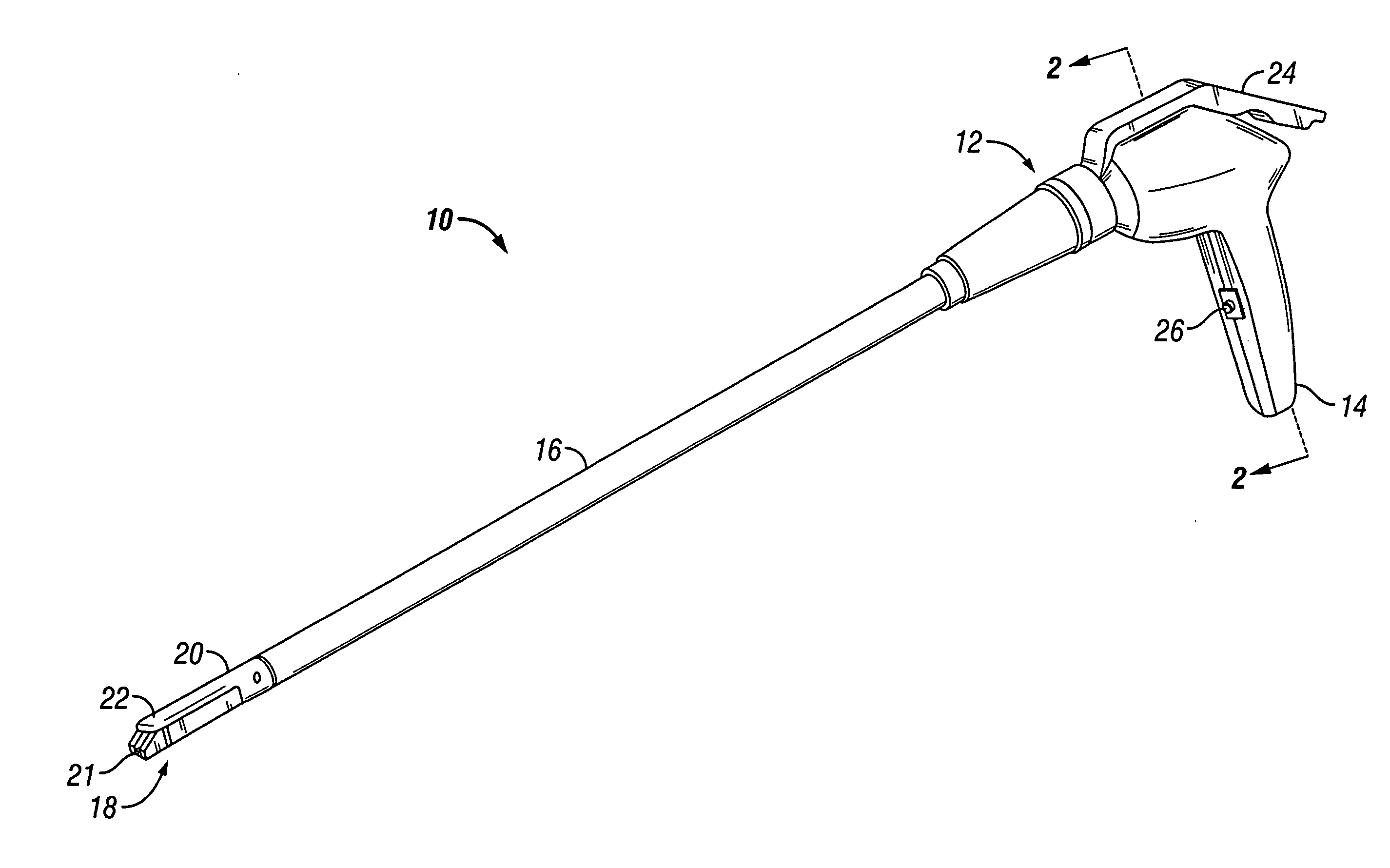
  • Battery powered surgical instrument
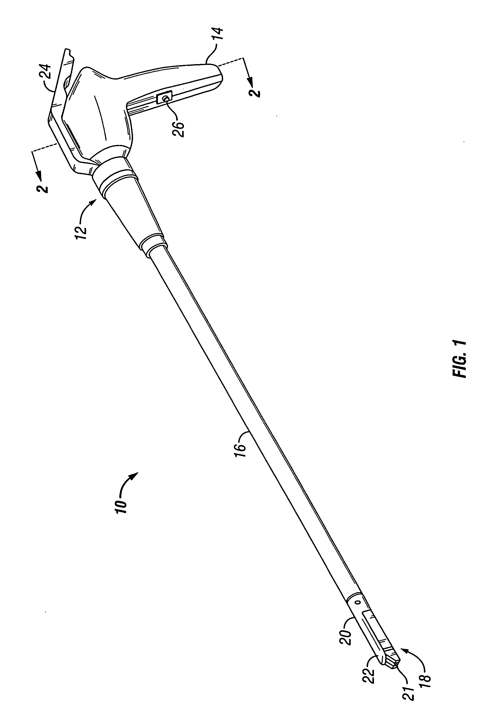
  • Battery powered surgical instrument
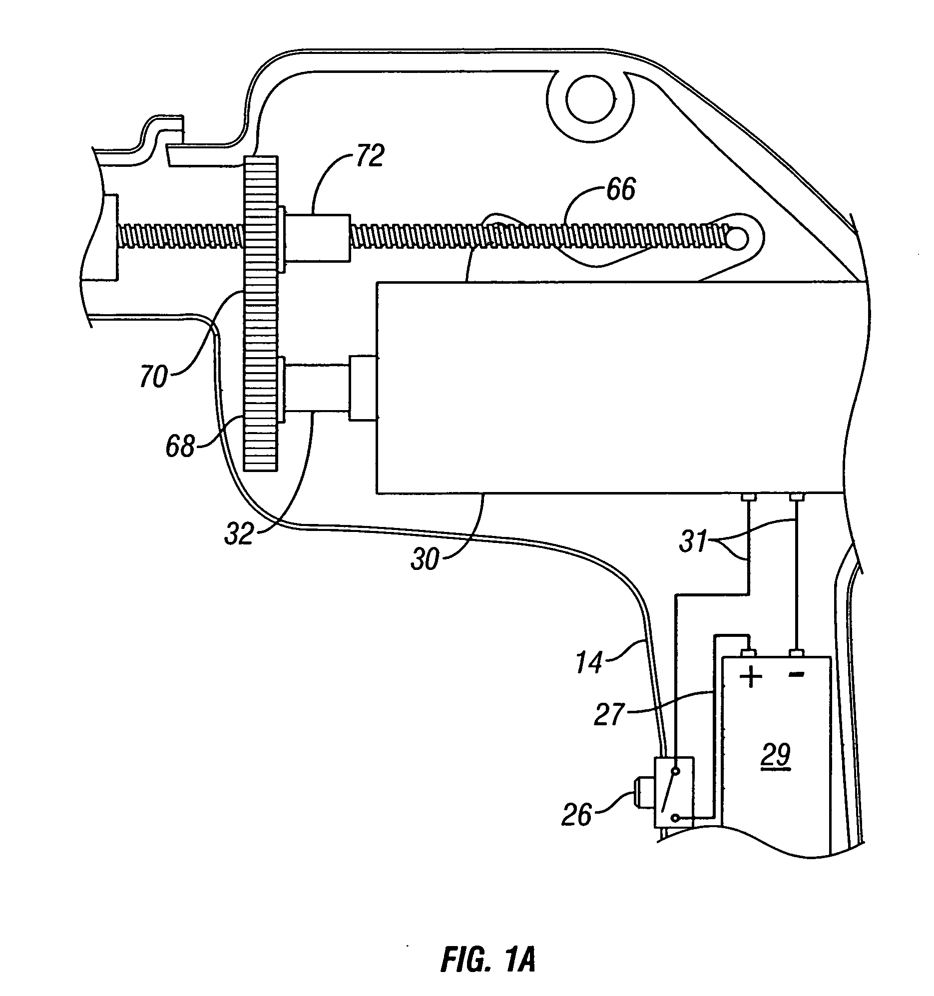
  • Battery powered surgical instrument

Examples


Embodiment Construction

[0027] In the drawings and in the description which follows, the term “proximal”, as is traditional, will refer to the end of the apparatus which is closest to the operator, while the term “distal” will refer to the end of the apparatus which is furthest from the operator.

[0028] The present disclosure shall be discussed in terms of both conventional and endoscopic procedures and apparatus. However, use herein of terms such as “endoscopic”, “endoscopically”, and “endoscopic portion”, among others, should not be construed to limit the present disclosure to an apparatus for use only in conjunction with an endoscopic tube. To the contrary, it is believed that the apparatus of present disclosure may find use in procedures in these and other uses including but not limited to where access is limited to a small incision such as arthroscopic and / or laparoscopic procedures, or any other conventional medical procedures known in the art.

[0029] Referring now to the figures, wherein like refere...


PUM

PropertyMeasurementUnit
diameteraaaaaaaaaa
degree of physical forceaaaaaaaaaa
degree of forceaaaaaaaaaa

Abstract

A surgical stapler has a handle assembly including a stationary handle and a trigger. The stapler also has a drive assembly with a body having a working end and a cam member supported on the working end. The cam member is positioned to translate relative to the anvil to maintain the anvil in the closed position during firing of the stapler. The trigger is operatively connected to a power cell. The power cell is operably connected to a motor of the drive assembly. The manipulation of the trigger actuates the power cell such that the power cell powers the drive assembly to effect translation of the cam member relative to the anvil. The stapler also has a channel for supporting the staple cartridge and the motor of the drive assembly controls the actuation sled supported within the cartridge. The actuation sled urges the plurality of staples from the cartridge when the anvil is in the closed position and in cooperative alignment with the staple cartridge.

Description

CROSS REFERENCE TO RELATED PATENT APPLICATIONS [0001] This patent application claims priority to U.S. Provisional Patent Application Ser. No. 60 / 687,406 to Viola, et al., filed on Jun. 3, 2005 which is herein incorporated by reference in its entirety. This patent application also claims priority to U.S. Provisional Patent Application Ser. No. 60 / 687,244 to Viola, et al., filed on Jun. 3, 2005 which is also herein incorporated by reference in its entirety. This patent application also relates to US. patent application Ser. No. ______ to Viola, et al., (Attorney Docket No. H-US-00378 (203-4731) filed contemporaneously with the instant patent application which is herein incorporated by reference in its entirety.BACKGROUND [0002] 1. Technical Field [0003] The present disclosure relates to surgical instruments. More particularly, the present disclosure relates to a surgical stapling device that has an improved and internally powered driving mechanism. [0004] 2. Background of the Related ...

Claims


Application Information

Patent Timeline
Patent Type & Authority Applications(United States)
IPC IPC(8): A61B17/04
CPCA61B17/07207A61B17/12A61B2017/00398A61B17/072A61B2017/2943A61B2017/320052A61B2017/00734A61B2017/00022A61B2017/00128A61B2017/00132A61B17/068A61B17/00234A61B2017/07214A61B2017/07257A61B2017/07271A61B2017/07285
Inventor VIOLA, FRANK J.KREHEL, GREGGPEDROS, GUIDO
Owner TYCO HEALTHCARE GRP LP
Learn More