Long magnetic sensor

a long-range magnetic sensor and sensor technology, applied in the field of long-range magnetic sensors, can solve the problems of degrading detection level, difficult to provide uniform output, and difficult to properly adjust the distance between the conveying roller and the long-range magnetic sensor

Active Publication Date: 2006-12-14
MURATA MFG CO LTD
View PDF7 Cites 35 Cited by
  • Summary
  • Abstract
  • Description
  • Claims
  • Application Information

AI Technical Summary

Benefits of technology

[0013] To overcome the problems described above, preferred embodiments of the present invention provide a long magnetic sensor in which no substantial gap is provided at any detection position in the longitudinal direction or in a direction that is substantially perpendicular thereto (moving direction of an detection object).
[0020] Accordingly, when the magnetic substance of the detection object reaches the position between the two adjacent magnetic resistance elements, the magnetic flux density of the magnetic fluxes passing through the magnetosensitive portions of the two magnetic resistance elements is changed, thereby enabling the detection of the magnetic substance.
[0021] In addition, since the positions of the plurality of magnetic resistance elements of the long magnetic sensor are linearly disposed, at the time of attaching the long magnetic sensor to a device, a diameter of a roller for moving the detection object, and a distance therebetween is easily adjusted. Further, since the magnetic poles of the adjacent magnets are heteropolar, the magnets are attracted to each other and do not repel each other. Accordingly, the magnets are easily housed in magnet housings of the case.
[0024] Accordingly, an ability to compensate the degradation of the output is enhanced at the end portions of the magnetosensitive portion of the magnetic resistance element, and the output characteristics similar to that of the conventional art are provided at the central portion of the magnetosensitive portion.
[0025] Since each of the magnetic resistance elements is arranged to span the adjacent magnets at each of positions where the plurality of magnets are adjacent to each other, the central portion of the magnet is located between the two magnetic resistance elements adjacent to each other. Generally, the magnetic flux density of the central portion of the magnet is high and stable as compared to the end portions thereof, the degradation of the detection level between the magnetic resistance elements is compensated for, thereby providing the detection level characteristics having a flat line over the longitudinal direction. In addition, even when the positions of the borders of the adjacent magnets are unevenly disposed, the variation in the detection level due to the unevenness is reduced.
[0026] Since the frames are arranged in the case such that the magnets are disposed along the alignment direction of the magnetic resistance elements in a zigzag manner in a plane parallel to the magnetosensitive portions of the magnetic resistance elements, in view of the design of the case structure for housing the magnetic resistance elements and the magnets, the positions of the magnets relative to the case are accurately determined, and consequently, the long magnetic sensor with the attachment accuracy being improved and the characteristics thereof being uniform is stably produced.

Problems solved by technology

However, the long magnetic sensor including the location where the detection level is degraded as shown in FIG. 8B is inappropriate when it is necessary to detect the magnetic substance pattern extending over the detection object.
In addition, since a correction amount of the positional deviation between the adjacent magnetic resistance elements may be different from that between other adjacent magnetic resistance elements depending on the accuracy of the moving speed of the detection object, it is difficult to provide a uniform output.
Accordingly, it is also difficult to properly adjust the distance between the conveying roller and the long magnetic sensor.

Method used


Image

  • Long magnetic sensor
  • Long magnetic sensor
  • Long magnetic sensor

Examples


Embodiment Construction

[0038] A configuration of a long magnetic sensor according to a first preferred embodiment of the present invention will be described below with reference to FIGS. 1A to 4B.

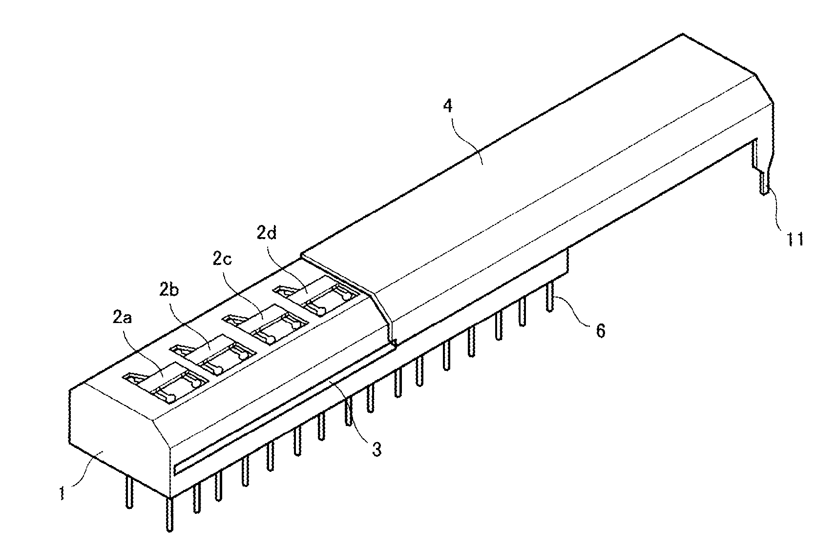
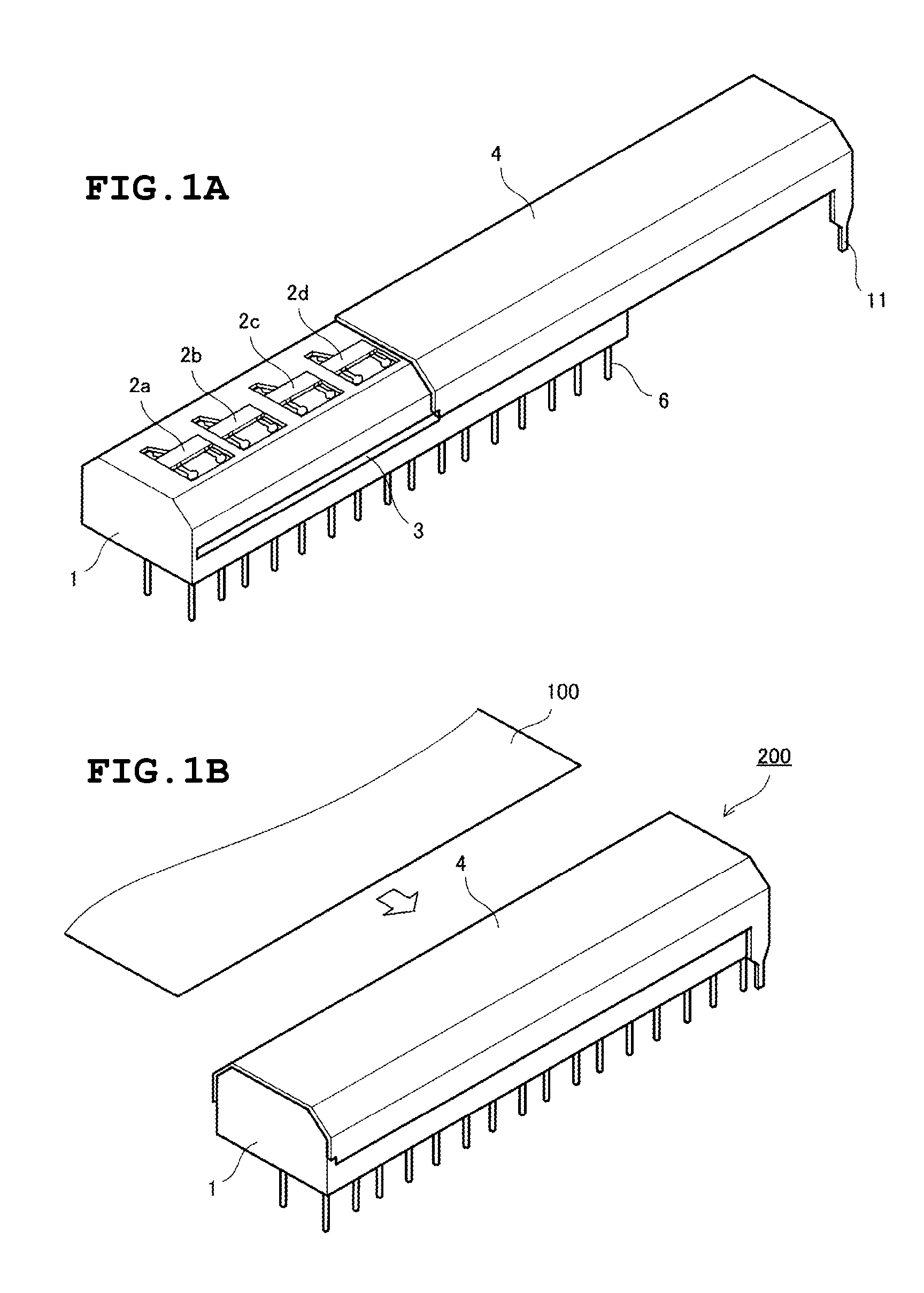
[0039]FIGS. 1A and 1B are external perspective views showing a long magnetic sensor, in which FIG. 1A shows the state in the middle of attaching a cover, and FIG. 1B shows the state with the cover attached. Magnetic resistance elements 2a, 2b, 2c, 2d . . . are mounted on the upper portion of a case 1 made of synthetic resin. Terminal pins 6 which are connected to the plurality of magnetic resistance elements 2a, 2b, 2c, 2d . . . project at the lower portion of the case 1. Claw-engaging grooves 3 are provided on both lateral sides of the case 1 along the longitudinal direction.

[0040] A metal cover 4 is provided with cover-fixing claws which are engaged with the claw-engaging grooves 3 of the case. When the cover 4 slides in the longitudinal direction while both the claw-engaging grooves 3 and the cover-fixing cla...


PUM


Abstract

A plurality of magnetosensitive portions of a plurality of magnetic resistance elements and a plurality of magnets are aligned substantially linearly to be perpendicular to a moving direction of a detection object, and directions of magnetic poles of the magnets are alternately inversed, such that directions of magnetic fluxes, which are perpendicular to a surface on which the magnetosensitive portions of the magnetic resistance elements are arranged, of the continuously disposed magnets, are alternately inverse.

Description

BACKGROUND OF THE INVENTION [0001] 1. Field of the Invention [0002] The present invention relates to a long magnetic sensor for detecting a magnetic pattern which is printed on, for instance, paper money. [0003] 2. Description of the Related Art [0004] Magnetic sensors for distinguishing, for example, paper money and securities on which predetermined patterns are printed using magnetic inks are disclosed in Japanese Patent No. 2921262 (Patent Document 1) and Japanese Unexamined Patent Application Publication No. 2003-107142 (Patent Document 2). A configuration of the long magnetic sensor disclosed in Patent Document 1 is shown in FIGS. 8A and 8B. FIG. 8A is a plan view showing magnetosensitive portions with a cover being removed. In this example, magnetic resistance elements (MR elements) 2a to 2e are provided with pairs of magnetosensitive portions 20a to 20e, respectively. The magnetic resistance elements 2a to 2e are aligned and fixed in a case 1. A detection object is arranged i...

Claims


Application Information

Patent Timeline
IPC IPC(8): G01R33/02G01D5/00G01R33/09G07D7/04
CPCG07D7/04G01R33/09
Inventor MINAMITANI, TAMOTSUSHINMURA, KOJIUEDA, MASAYANISHIKAWA, MASANAGA
Owner MURATA MFG CO LTD
Why Eureka
Try Eureka