Supercharge Your Innovation With Domain-Expert AI Agents!

Apparatus and method for Raman gain control

Active Publication Date: 2006-12-14
XYLON LLC
View PDF87 Cites 3 Cited by
  • Summary
  • Abstract
  • Description
  • Claims
  • Application Information

AI Technical Summary

Benefits of technology

[0014] In one aspect of the invention, a Raman gain control apparatus for counterpropagating pump and signal based on backscattered pump power measurements is taught.
[0015] In another aspect of the invention, a Raman gain control method for counterpropagating pump and signal based on backscattered pump power measurements is taught.
[0016] In another aspect of the invention, a Raman gain control apparatus for co-propagating pump and signal based on signal input power measurements is t

Problems solved by technology

The laser may be directly modulated with a data train with an advantage of low cost, and a disadvantage of low reach and capacity performance.
In a Raman amplifier that uses the fiber span, this control method is slow because of the large distance between the input and the output of the fiber span.
This method is not optimal, however, because extra hardware is required, and the additional optical signal limits the reach and capacity of the optical transport system.

Method used


Image

  • Apparatus and method for Raman gain control
  • Apparatus and method for Raman gain control
  • Apparatus and method for Raman gain control

Examples


Embodiment Construction

[0029] While the making and using of various embodiments of the present invention are discussed in detail below, it should be appreciated that the present invention provides many applicable inventive concepts which can be embodied in a wide variety of specific contexts. The specific embodiments described herein are merely illustrative of specific ways to make and use the invention and do not delimit the scope of the invention.

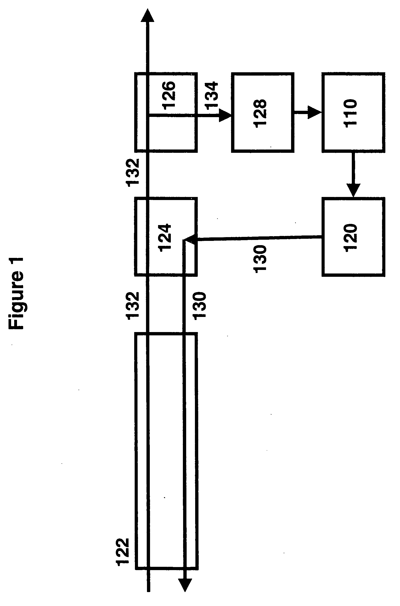
[0030] In FIG. 1 is shown a block diagram of a Raman gain control apparatus for counterpropagating pump and signal based on signal output power measurements. The Raman gain control apparatus comprises a Raman pump laser 120 that is optically coupled to a wavelength selective optical coupler 124. Wavelength selective coupler 124 is further optically coupled to fiber span 122 and optical tap 126. The apparatus also comprises optical power meter 128, and a Raman gain control unit 110.

[0031] Raman pump laser 120 may be implemented as a sufficiently powerful laser...


PUM


Abstract

The invention pertains to optical fiber transmission systems, and is particularly relevant to optical transport systems employing Raman optical amplifiers. In particular the invention teaches an apparatus and method to control the Raman gain based upon power measurements at one end of the transmission fiber.

Description

CROSS-REFERENCE TO RELATED APPLICATION [0001] This application claims priority to U.S. Provisional Application Ser. No. 60 / 386,086, entitled “Method and Apparatus for Raman Gain Control”, by Eiselt, filed Jun. 4, 2002.TECHNICAL FIELD OF THE INVENTION [0002] The present invention relates, in general, to the field of optical communications, and in particular to, an optical transport system that uses Raman optical amplifiers. In particular the invention teaches an apparatus and method to control the Raman gain based upon power measurements at one end of the transmission fiber. BACKGROUND OF THE INVENTION [0003] A goal of many modern long haul optical transport systems is to provide for the efficient transmission of large volumes of voice traffic and data traffic over trans-continental distances at low costs. Various methods of achieving these goals include time division multiplexing (TDM) and wavelength division multiplexing (WDM). In time division multiplexed systems, data streams com...

Claims


Application Information

Patent Timeline
IPC IPC(8): H01S3/00H01S3/13H01S3/30
CPCH01S3/302H01S3/1301H01S3/06754H01S3/1305H01S3/13013
Inventor EISELT, MICHAEL H.
Owner XYLON LLC
Features
  • R&D
  • Intellectual Property
  • Life Sciences
  • Materials
  • Tech Scout
  • Unparalleled Data Quality
  • Higher Quality Content
  • 60% Fewer Hallucinations
Learn More