Optical disk drive, optical disk apparatus, and method for driving the apparatus

a technology of optical disk drive and optical disk, which is applied in the direction of digital signal error detection/correction, instruments, recording signal processing, etc., can solve the problems of fluctuation of sil caused, and achieve the effect of preventing reliably the collision between a light focusing element and an optical disk

Inactive Publication Date: 2006-12-14
SONY CORP
View PDF7 Cites 18 Cited by
  • Summary
  • Abstract
  • Description
  • Claims
  • Application Information

AI Technical Summary

Benefits of technology

[0024] As described above, according to the present invention, collision between a light focusing element and an optical disk can be prevented reliably.

Problems solved by technology

In an apparatus disclosed in Patent Document 2, however, there is concern about the fluctuation of the SIL caused by the initial velocity of the SIL upon starting the approach.

Method used


Image

  • Optical disk drive, optical disk apparatus, and method for driving the apparatus
  • Optical disk drive, optical disk apparatus, and method for driving the apparatus
  • Optical disk drive, optical disk apparatus, and method for driving the apparatus

Examples


Embodiment Construction

[0035] An embodiment of the present invention will now be described below with reference to the drawings.

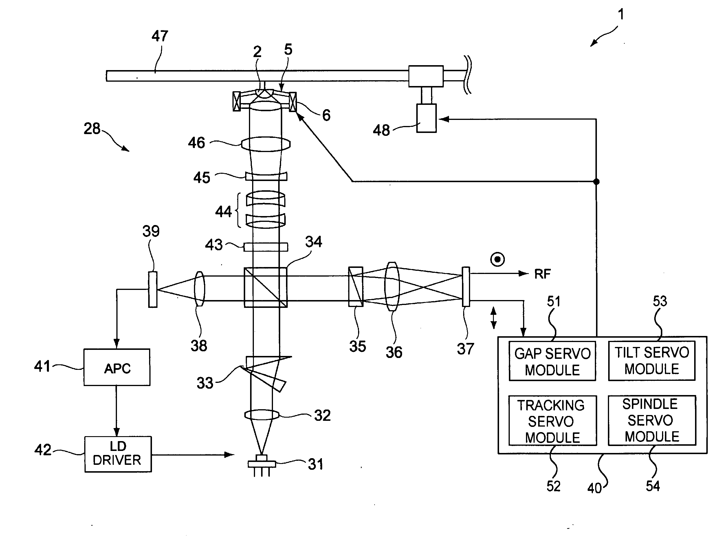
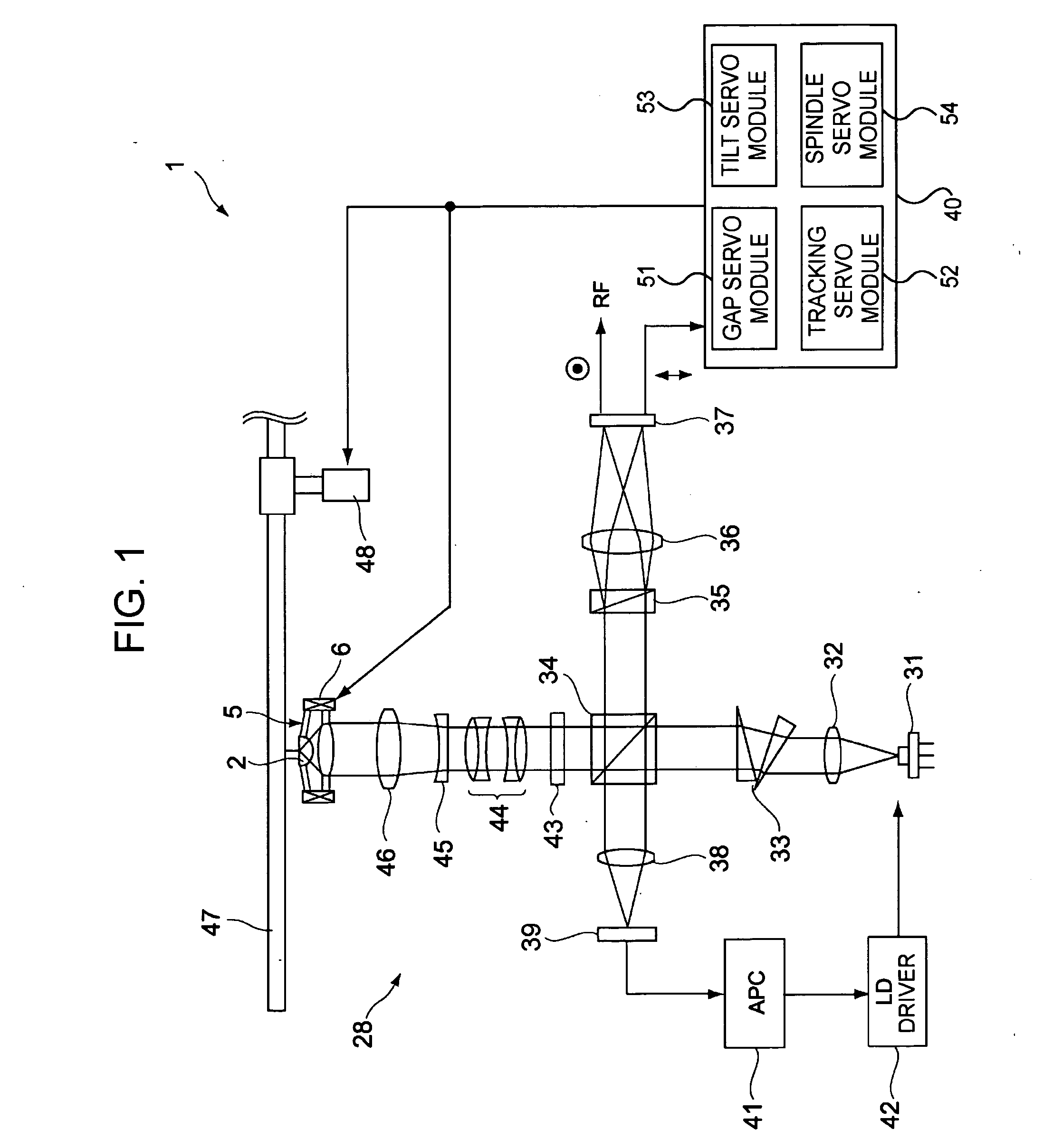
[0036]FIG. 1 is a diagram of the structure of an optical disk drive according to one embodiment of the present invention. An optical disk drive 1 includes an optical head 28, a servo controller 40, and a spindle motor 48. The optical head 28 includes: a laser diode (LD) 31, serving as a light source; collimator lenses 32 and 46; an anamorphic prism pair 33 for shaping laser light; a beam splitter (BS) 34; a quarter wave plate (QWP) 43; an achromatic lens 44; a diverging lens 45 that diverges a laser beam; a Wollaston prism 35; converging lenses 36 and 38; a light focusing element 5; photodetectors (PDs) 37 and 39; an automatic power controller (APC) 41; and an LD driver 42.

[0037] The Wollaston prism 35 consists of two prisms. The Wollaston prism 35 permits incident light to pass through as two beams which are mutually perpendicularly polarized. The PD 37 outputs an RF read sign...


PUM

PropertyMeasurementUnit
distanceaaaaaaaaaa
gap lengthaaaaaaaaaa
voltageaaaaaaaaaa

Abstract

An optical disk drive includes a light source, a light focusing element, a light-focusing-element moving mechanism, a detecting unit, a holding unit, and first and second control units. The light focusing element arranged so as to be opposed to a disk on which a signal is recordable is capable of focusing light emitted from the light source as near-field light on the disk. The detecting unit detects a state where the moving mechanism approaches the light focusing element to the disk such that the light is focused as near-field light on the disk and outputs a detection signal upon detection. The holding unit holds a voltage applied to the mechanism in response to the detection signal and is capable of releasing the held voltage. The first and second control units perform first and second control operations to control the distance between the light focusing element and the disk.

Description

CROSS REFERENCES TO RELATED APPLICATIONS [0001] The present invention contains subject matter related to Japanese Patent Application JP 2005-150743 filed in the Japanese Patent Office on May 24, 2005, the entire contents of which are incorporated herein by reference. BACKGROUND OF THE INVENTION [0002] 1. Field of the Invention [0003] The present invention relates to an optical disk drive for performing at least one of writing and reading of signals using near-field light, an optical disk apparatus mounted with the drive, and a method for driving the apparatus. [0004] 2. Description of the Related Art [0005] To increase the recording density of an optical disk on which data is written or read using laser light, an optical disk apparatus for writing or reading signals using near-field light has recently been proposed. According to a proposed technique for the optical disk apparatus utilizing near-field light, a gap between an optical disk and the end surface of a solid immersion lens ...

Claims


Application Information

Patent Timeline
Patent Type & Authority Applications(United States)
IPC IPC(8): G11B7/00
CPCG11B7/08511G11B7/1387G11B7/0938G11B7/085G11B7/09
Inventor ISHIMOTO, TSUTOMU
Owner SONY CORP
Why Eureka
Try Eureka