System and method for deriving IPv6 scope identifiers and for mapping the identifiers into IPv6 addresses

a technology of scope identifiers and mapping methods, applied in the field of computer networks, can solve the problems of imposing complexities, limited number of available addresses, and significant complexity for all, and achieve the effect of high speed and efficient processing

Inactive Publication Date: 2006-12-14
CISCO TECH INC
View PDF11 Cites 86 Cited by
  • Summary
  • Abstract
  • Description
  • Claims
  • Application Information

AI Technical Summary

Benefits of technology

[0027] Briefly, the invention relates to a system and method that utilizes Virtual Local Area Network (VLAN) designations as Internet Protocol version 6 (IPv6) link identifiers, and that maps VLAN designations to IPv6 site identifiers (IDs). The system also generates a compacted or encoded look-up address based on the destination address specified within a received network message, such as an IPv6 packet. The invention is preferably implemented at an intermediate network device, such as a router, having a plurality of interfaces for receiving and forwarding packets, and a route processor for making forwarding decisions for received packets. The route processor includes a routing engine, a routing table, a forwarding information base (FIB), a VLAN store and a site ID store. At least some of the router's interfaces, moreover, are preferably associated with VLAN designations, and the site ID store is pre-configured with a mapping of VLAN designations to site IDs. In particular, each VLAN designation is mapped to just one site ID, but more than one VLAN designation may be mapped to the same site ID. The look-up address generated for a packet is applied to the FIB in order to generate a forwarding decision for the packet in an efficient and high-speed manner.

Problems solved by technology

One of the primary deficiencies is the limited number of available addresses.
The definition of multiple scopes for both unicast and multicast addresses imposes complexities on intermediate network devices, such as routers, which need to process and forward packets from their interfaces at high rates of speed.
This can impose significant complexities for all but node-local and global multicast addresses.
The remaining twelve kinds of scoped multicast addresses, however, can impose complex processing requirements.
This approach, however, as recognized in the Internet Draft document itself, increases protocol processing time, thereby reducing the efficiency of the intermediate device.
As there are twelve possible non-global multicast scopes, each potentially requiring several tables, the introduction of scoped multicast addresses substantially increases the complexity of packet processing and forwarding, leading to a likely reduction in throughput.

Method used


Image

  • System and method for deriving IPv6 scope identifiers and for mapping the identifiers into IPv6 addresses
  • System and method for deriving IPv6 scope identifiers and for mapping the identifiers into IPv6 addresses
  • System and method for deriving IPv6 scope identifiers and for mapping the identifiers into IPv6 addresses

Examples


Embodiment Construction

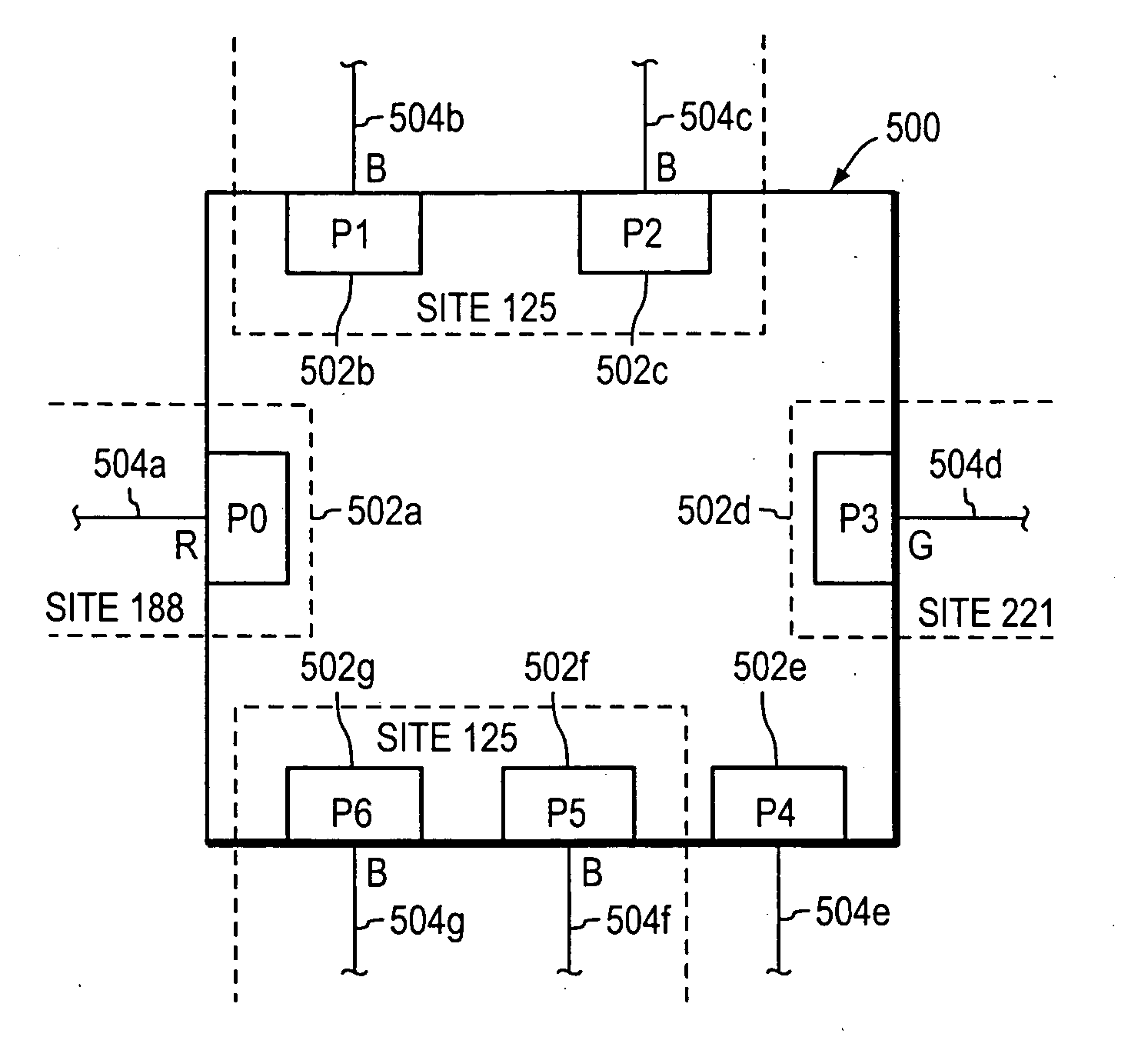
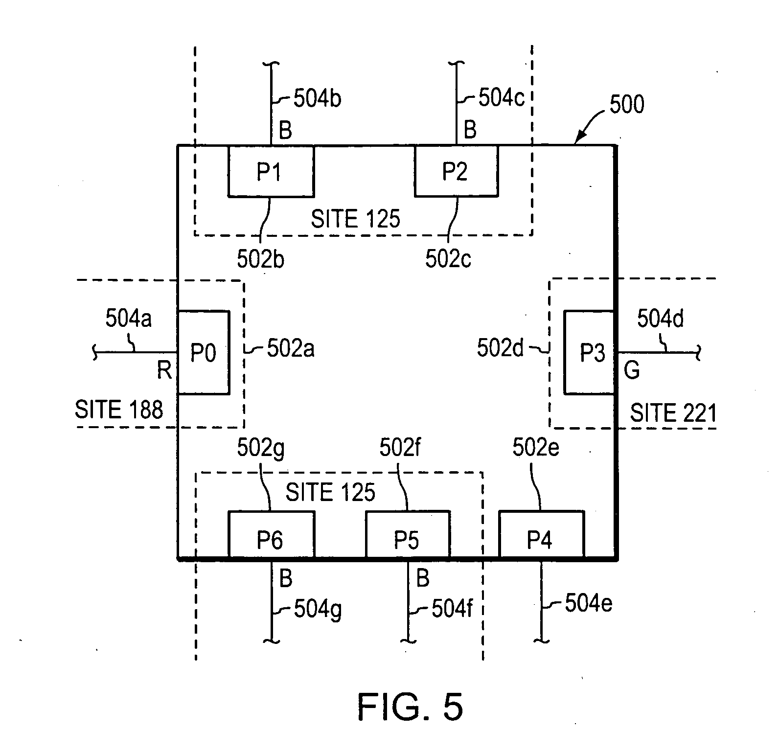
[0039]FIG. 5 is a highly schematic illustration of an intermediate network device 500 in accordance with the present invention. Device 500 includes a plurality of interfaces or ports 502a-g from which network messages can be received and forwarded. Each port, moreover, may be identified by a corresponding port identifier, e.g., P0-P6. Coupled to each port 502a-g is a respective link 504a-g. As described herein, device 500 is configured to forward network messages, e.g., packets and / or frames, originated by a source entity and received by the device 500 on a first port, e.g., P1, onto a second port, e.g., P5 for receipt by a destination entity.

[0040] Device 500 is preferably disposed within a computer network (not shown), and each port or interface of device 500 may be associated with one or more Virtual Local Area Network (VLAN) designations or identifiers (IDs) defined within the network. For example, port 502a or P0, which is an access port, is associated with the red (R) VLAN ID...


PUM


Abstract

A system and method are employed for forwarding multicast packets among a plurality of interfaces. A multicast packet having a scope value and a multicast group identifier (ID) value is received on an inbound interface. A VLAN designation associated with the inbound interface is identified. If the scope value in the received multicast packet indicates that the multicast packet has a link-local scope, a look-up address is generated that includes the identified VLAN designation and the multicast group ID value of the multicast packet. If the scope value in the received multicast packet indicates that the multicast packet has a site-local scope or an organization-local scope, the identified VLAN designation is used to retrieve a site identifier associated with the VLAN designation, and a look-up address is generated that includes the retrieved site identifier and the multicast group ID value. Finally, the look-up address is used to render a forwarding decision for the multicast packet.

Description

CROSS-REFERENCE TO RELATED APPLICATION [0001] This application is a continuation of commonly assigned copending U.S. patent application Ser. No. 10 / 140,485, which was filed on May 7, 2002, by Claudio Desanti for a SYSTEM AND METHOD FOR DERIVING IPV6 SCOPE IDENTIFIERS AND FOR MAPPING THE IDENTIFIERS INTO IPV6 ADDRESSES.[0002] This application is also related to the following co-pending, commonly owned U.S. patent application: [0003] U.S. patent application Ser. No. 09 / 964,702 entitled SYSTEM AND METHOD FOR MAPPING AN INDEX INTO AN IPV6 ADDRESS, filed Sep. 27, 2001. BACKGROUND OF THE INVENTION [0004] 1. Field of the Invention [0005] This invention relates to computer networks and, more specifically, to the making of forwarding decisions for network messages. [0006] 2. Background Information [0007] Computer networks typically comprise a plurality of interconnected entities. An entity may consist of any device, such as a computer or end station, that “sources” (i.e., transmits) or “sink...

Claims


Application Information

Patent Timeline
Patent Type & Authority Applications(United States)
IPC IPC(8): H04L12/56
CPCH04L12/18H04L45/742H04L12/4641
Inventor DESANTI, CLAUDIO
Owner CISCO TECH INC
Why Eureka
Try Eureka