Packet communication method and packet communication device

a packet communication and packet communication technology, applied in multiplex communication, code conversion, coding, etc., can solve the problems of error detection working only on ordinary data packets, increasing costs, and restricting throughput,

Inactive Publication Date: 2006-12-14
NIPPON TELEGRAPH & TELEPHONE CORP
View PDF4 Cites 38 Cited by
  • Summary
  • Abstract
  • Description
  • Claims
  • Application Information

AI Technical Summary

Benefits of technology

[0035] Performing a plurality of error detection code operations on a received packet as described above makes it possible to recognize the kind of the received packet by a single comp...

Problems solved by technology

That is, in the conventional systems, the maximum size of data that can be transmitted by one MAC frame cannot be utilized effectively, which restricts increase in throughput.
On the other hand, although a reception-side station should reconstruct original data frames from received data packets, it cannot do so unless some measure is taken because the received data packets have a packet format that is not expected conventionally.
That is, from the viewpoint of the IP layer, a problem arises unless the head portion of the data field of each received data frame is header information that is necessary for reconstruction of an original IP packet.
However, in the data packets that have been reconfigured in the transmitting side by the above-described frame patching or aggregation, the header information that is necessary for reconstruction of an original IP packet may be located at a position othe...

Method used


Image

  • Packet communication method and packet communication device
  • Packet communication method and packet communication device
  • Packet communication method and packet communication device

Examples


embodiment 1

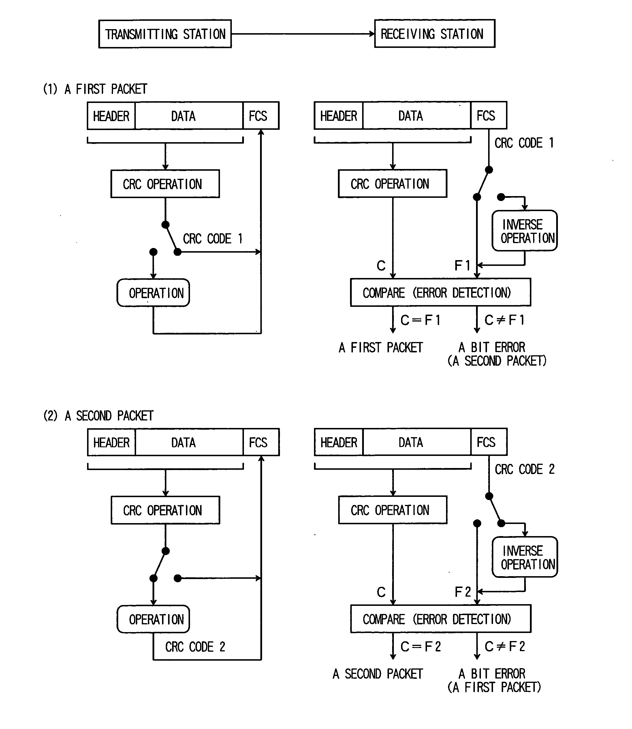
[0156]FIG. 1 shows a packet communication method according to a first embodiment of the present invention. In the first to seventh embodiments, it is assumed that a first packet and a second packet to be discriminated from each other are, for example, a standard-format data packet and a special-format data packet or a control packet 1 to be used for setting of mode 1 and a control packet 2 to be used for setting of mode 2.

[0157] As shown in FIG. 1, when a transmitting station transmits a first packet, a CRC code 1 generated by a prescribed CRC operation is put into the FCS field (see part (1)). When the transmitting station transmits a second packet, a CRC code 2 obtained by converting, through a prescribed operation, a CRC code that is generated by the prescribed CRC operation is put into the FCS field (see part (2)). The prescribed operation includes at least one of the bit reversal of all or part of the bits of the CRC code 1, the addition or subtraction of a prescribed value to...

embodiment 2

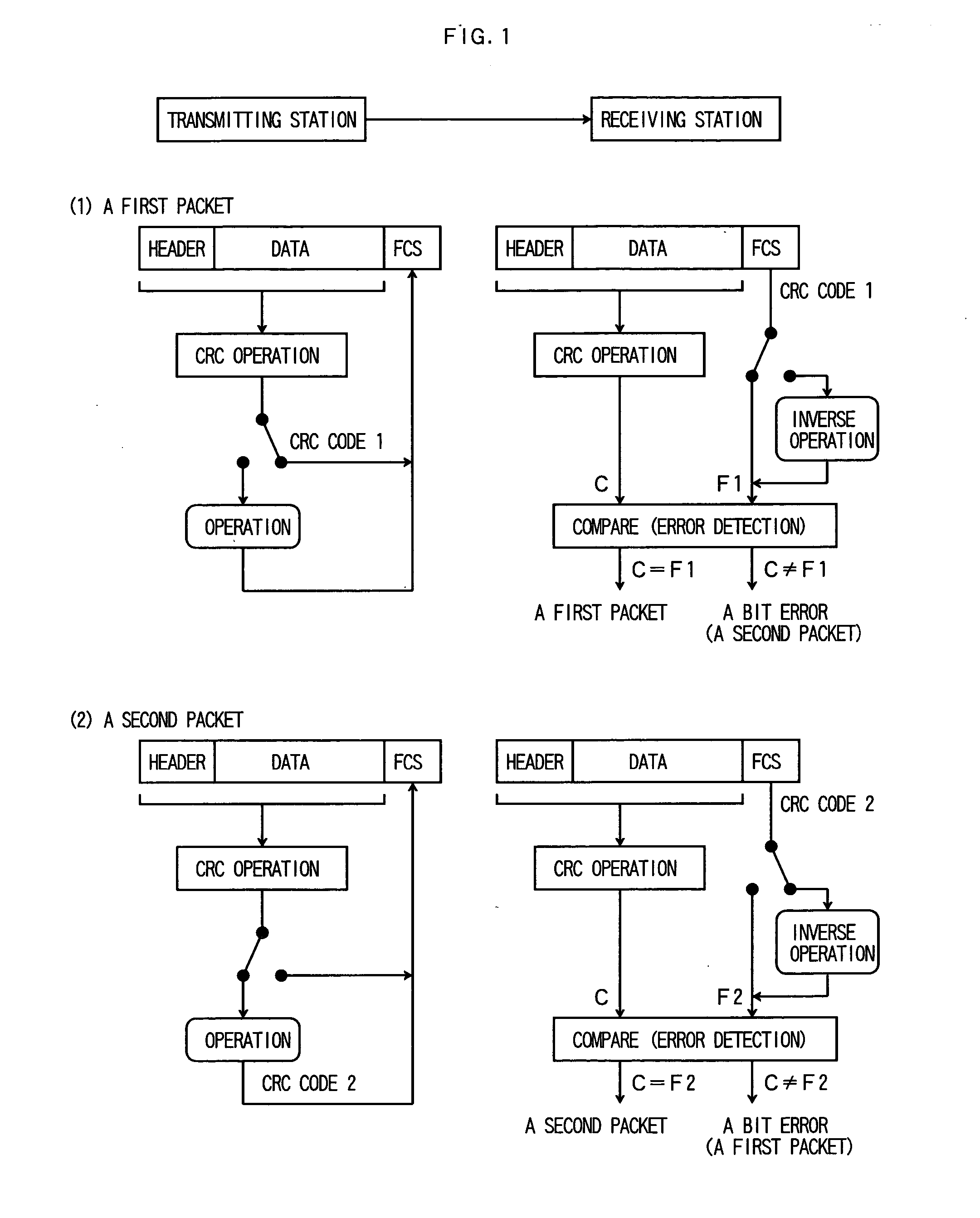
[0160]FIG. 2 shows a packet communication method according to a second embodiment of the invention. As shown in FIG. 2, when a transmitting station transmits a first packet, a CRC code 1 generated by a prescribed CRC operation is put into the FCS field (see part (1)). When the transmitting station transmits a second packet, a CRC code 2 obtained by converting, through a prescribed operation, a CRC code that is generated by the prescribed CRC operation is put into the FCS field (see part (2)).

[0161] A receiving station performs error detection on a received packet. More specifically, a CRC code (C) generated by the prescribed CRC operation is compared with a CRC code (F1) contained in the FCS field of the received packet as well as a CRC code (F2) that is obtained by subjecting the CRC code contained in the FCS field of the received packet to the inverse of the operation performed in the transmitting side. If the codes C and F1 coincide with each other, the received packet is recogn...

embodiment 3

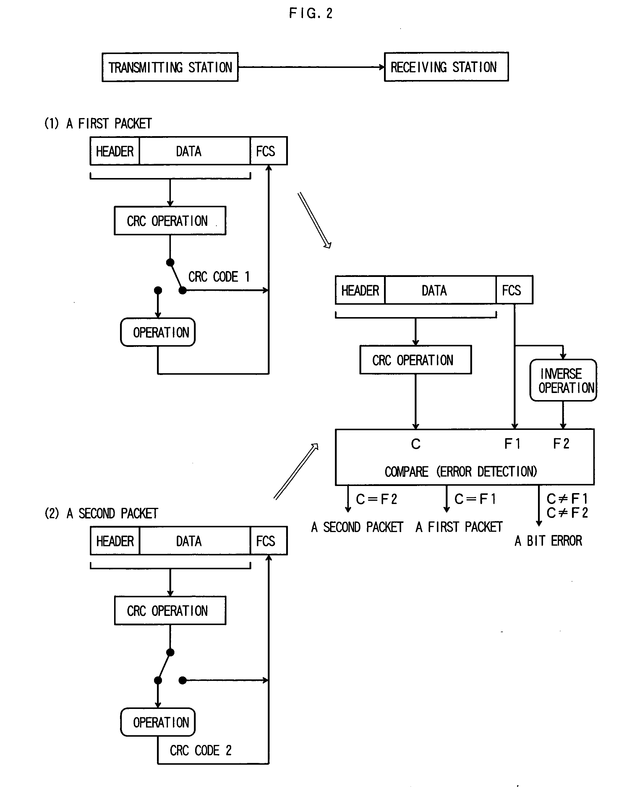
[0163]FIG. 3 shows a packet communication method according to a third embodiment of the invention. As shown in FIG. 3, when a transmitting station transmits a first packet, a CRC code 1 generated by a prescribed CRC operation is put into the FCS field (see part (1)). When the transmitting station transmits a second packet, a CRC code 2 obtained by converting, through a prescribed operation, a CRC code that is generated by the prescribed CRC operation is put into the FCS field (see part (2)).

[0164] A receiving station performs error detection on a received packet. More specifically, a CRC code (C1) generated by the prescribed CRC operation is compared with a CRC code (F) contained in the FCS field of the received packet. If the codes C1 and F coincide with each other, the received packet is recognized as a first packet and subjected to reception processing. On the other hand, if the codes C1 and F do not coincide with each other, a CRC code (C2) that is obtained by subjecting the CR...


PUM


Abstract

A first communication node, which transmits a packet including a data field and an FCS field, selectively transmits, to a second communication node, a first packet containing, in the FCS field, a first error detection code generated by performing a prescribed error detection code operation on a transmission packet or a second packet containing, in the FCS field, a second error detection code obtained by performing a prescribed operation on the first error detection code. The second communication node compares an error detection code C generated by performing the prescribed error detection code operation on a received packet with an error detection code F1 contained in the FCS field of the received packet, performs reception processing on the received packet with the understanding that it is classified as the first packet if the error detection codes C and F1 coincide with each other, compares the error detection code C generated by performing the prescribed error detection code operation on the received packet with an error detection code F2 obtained by performing an inverse operation for returning a result of the prescribed operation to an original on the error detection code F1 contained in the FCS field of the received packet, and performs reception processing on the received packet with the understanding that it is classified as the second packet if the error detection codes C and F2 coincide with each other.

Description

TECHNICAL FIELD [0001] The present invention relates to a packet communication method and a packet communication apparatus that are used for transmitting plural kinds of packets between communication nodes. BACKGROUND ART [0002] In radio packet communication systems in which plural kinds of packets are transmitted, it is necessary to recognize the kind of a received packet and perform processing suitable for it. One method for communicating identification information such a packet is to manipulate a CRC (cyclic redundancy check) code for error detection that is contained in the FCS (frame check sequence) field of the packet (Japanese Patent Gazette No. 3,349,861). [0003] More specifically, to discriminate between two kinds of packets (e.g., a data packet and a control packet), an ordinary CRC code generated by a prescribed CRC operation is contained in the FCS field of one kind of packet and a prescribed code, instead of a CRC code, is contained in the FCS field of the other kind of...

Claims


Application Information

Patent Timeline
IPC IPC(8): H04J3/24H04L1/00H04L1/16H04L1/22H04L29/02H04W28/04H04W72/04
CPCH04L1/1671H04L1/0025H04L1/00H04W28/04
Inventor NAGATA, KENGOKUMAGAI, TOMOAKIOTSUKI, SHINYASAITO, KAZUYOSHIAIKAWA, SATORUYOSHIOKA, MASAFUMI
Owner NIPPON TELEGRAPH & TELEPHONE CORP
Why Eureka
Try Eureka