Micromachined Capacitive Microphone

Inactive Publication Date: 2006-12-14
GENERAL MEMS CORP
View PDF10 Cites 122 Cited by
  • Summary
  • Abstract
  • Description
  • Claims
  • Application Information

AI Technical Summary

Benefits of technology

[0007] It is an object of the present invention to provide a micromachined capa

Problems solved by technology

However, achieving a large dynamic range and a high sensitivity can be conflicting goals, since large sound pressures may cause a diaphragm to collapse under its voltage bias if it is very comp

Method used


Image

  • Micromachined Capacitive Microphone
  • Micromachined Capacitive Microphone
  • Micromachined Capacitive Microphone

Examples


Embodiment Construction

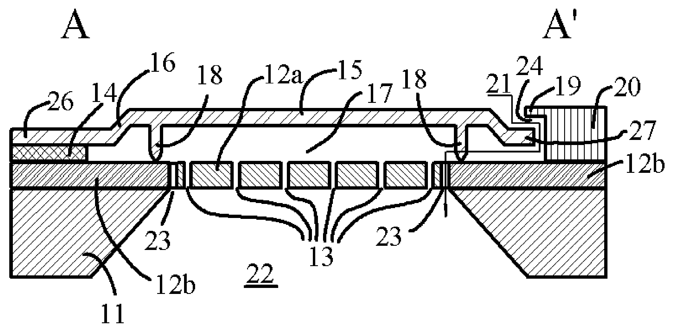
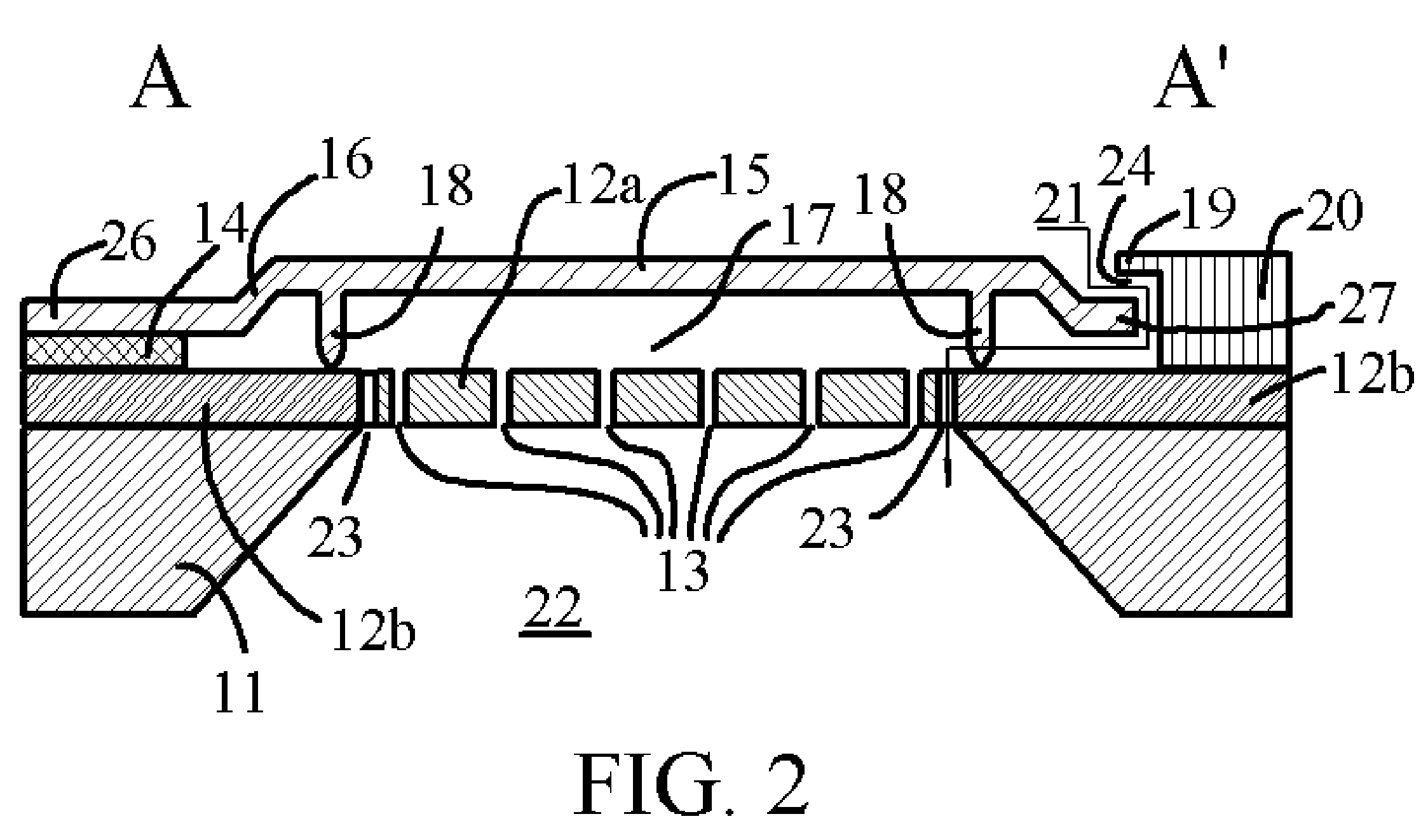
[0030] For micromachined capacitive microphones, its sensitivity is largely dominated by the intrinsic stress of diaphragm. When the size of the diaphragm is fixed, its mechanical sensitivity is inversely proportional to the intrinsic stress in the diaphragm. A diaphragm has the highest mechanical sensitivity when it is free to move in a plane that is perpendicular to its own plane as a piston. On the other hand, certain level of intrinsic stress needs to be maintained in the diaphragm such that its resonant frequency is far from the frequency range it operates, thereby exhibiting a flat frequency response in the audio frequency range. In addition, the mechanical strength of the diaphragm also requires the diaphragm to be stiffer. These seemed conflicting requirements suggest that a micromachined capacitive microphone needs to have ways to tightly control its intrinsic stress to meet the final product requirements. One technique to release or control the intrinsic stress in the diap...


PUM


Abstract

This invention relates to a micromachined capacitive microphone having a shallowly corrugated diaphragm that is anchored at one or more locations on the support has a plurality of dimples to support itself and rest freely on the perforated backplate. The diaphragm whose ends are not anchored is bounded by the taps of edge rail. Also disclosed includes: a fixed perforated backplate having one or more regions; an adjustable cantilever formed by the diaphragm, the support and the backplate; a plurality of dimples maintaining vertical separation between diaphragm and backplate; and the patterning of conductor electrodes carried by diaphragm and backplate.

Description

CROSS REFERENCE TO RELATED APPLICATION [0001] U.S. Pat. Nos. 5,146,435; 5,452,268; 6,535,460; 6,847,090; 6,870,937.BACKGROUND OF THE INVENTION [0002] Micromachined capacitive microphone has been an attractive topic for many publications and disclosures. The batch processing of micromachining enables the production of these microphones to be made inexpensively and in large quantity. Compared with traditional capacitive microphones, micromachined capacitive microphones offer a much larger set of parameters for optimization as well as ease for on-chip electronic integration. [0003] In many publications such as U.S. Pat. Nos. 5,146,435; 5,452,268; 6,847,090; and 6,870,937, the movable diaphragm of a micromachined capacitive microphone is either supported by a substrate or insulative supports such as silicon nitride, silicon oxide and polyimide. The supports engage the edge of the diaphragm, and a voltage is applied between the substrate and the surface of the diaphragm causing the diaph...

Claims


Application Information

Patent Timeline
IPC IPC(8): H04R25/00
CPCB81B3/0072H04R19/005B81B2203/0127B81B2201/0257
Inventor WANG, YUNLONGATA, ERHANWU, GUANGHUA
Owner GENERAL MEMS CORP
Why Eureka
Try Eureka