Thin film type microphone array

A microphone array and film-type technology, which is applied in the field of microphones, can solve the problems that the volume of the device cannot be reduced and the cost performance needs to be improved, and achieve the effects of simple manufacturing process, light weight and reduced number of parts

Active Publication Date: 2011-07-27
SHENZHEN HORN AUDIO
View PDF7 Cites 4 Cited by
  • Summary
  • Abstract
  • Description
  • Claims
  • Application Information

AI Technical Summary

Problems solved by technology

For the electret condenser microphone, a large air resonance cavity is required, so the device volume cannot be reduced
For silicon microphones, the cost performance needs to be improved, and the packaging process and quality problems need to be improved urgently

Method used


Image

  • Thin film type microphone array
  • Thin film type microphone array
  • Thin film type microphone array

Examples


Embodiment 1

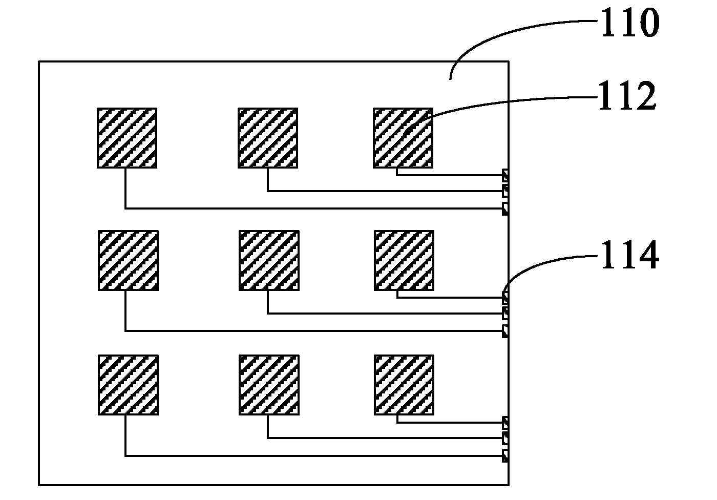
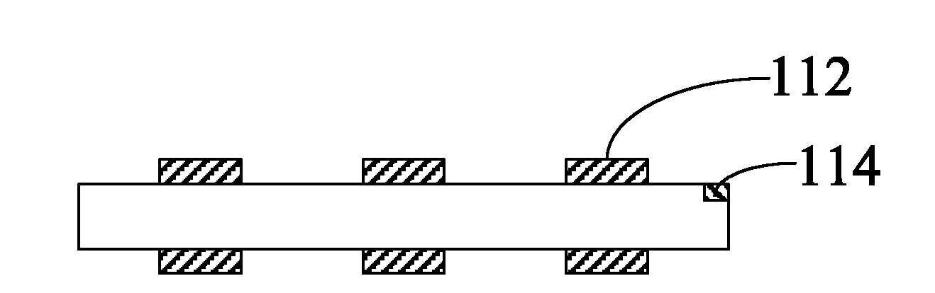
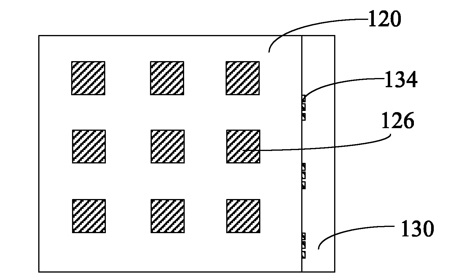
[0027] Please combine Figure 1-Figure 4 , the film-type microphone array in this embodiment includes a piezoelectric electret film 110 , a circuit board assembly 120 and a connector 130 .

[0028] The piezoelectric electret film 110 is a porous polymer film with a thickness ranging from tens to hundreds of microns. Such as figure 1 and figure 2 As shown, the piezoelectric electret film 110 in this embodiment is square, and 3×3 block electrodes are correspondingly arranged on both sides to form an electrode array 112 . Each pair of bulk electrodes corresponding to both sides and the piezoelectric electret film between them jointly form a piezoelectric microphone unit. This embodiment includes 9 piezoelectric microphone units. The piezoelectric electret film 110 is provided with an electrode connection terminal 114 at the edge that is electrically connected to each bulk electrode on one side.

[0029] The porous polymer film deposits positive and negative charges on the u...

Embodiment 2

[0038] Such as Figure 6 and Figure 7 As shown, the film-type microphone array of this embodiment includes a piezoelectric electret film 210 and a circuit board assembly 220 .

[0039] The piezoelectric electret film 210 is a porous polymer film with a thickness ranging from tens to hundreds of microns. The piezoelectric electret film 210 in this embodiment is square, and 3×3 block electrodes are correspondingly arranged on both sides to form an electrode array 212 . Each pair of bulk electrodes corresponding to both sides and the piezoelectric electret film between them jointly form a microphone unit. This embodiment includes 9 microphone units. The piezoelectric electret film 210 is provided with a first electrode connection end 214 and a second electrode connection end 216 at the edge, which are electrically connected to the electrodes on both sides.

[0040] The circuit board assembly 220 of this embodiment is fixed on the blank area of ​​the piezoelectric electret fi...

Embodiment 3

[0043] Such as Figure 8 and Figure 9 As shown, the film-type microphone array of this embodiment includes a piezoelectric electret film 310 , a circuit board assembly 320 and a connector 330 .

[0044] The piezoelectric electret film 310 is a porous polymer film with a thickness ranging from tens to hundreds of microns. The piezoelectric electret film 310 in this embodiment is square, and 3×3 block electrodes are correspondingly arranged on both sides to form an electrode array 312 . Each pair of bulk electrodes corresponding to both sides and the piezoelectric electret film between them jointly form a microphone unit. This embodiment includes 9 microphone units. The piezoelectric electret film 310 is provided with a first electrode connection end 314 and a second electrode connection end 316 at the edge, which are electrically connected to the electrodes on both sides.

[0045] The circuit board assembly 320 is provided with a microphone circuit (not shown in the figure...


PUM


Abstract

The invention relates to a thin film type microphone array, comprising a piezoelectric electret thin film and a circuit board component, wherein the piezoelectric electret thin film is a porous thin polymer film; electrode arrays are correspondingly arranged at two sides of the piezoelectric electret thin film; a microphone circuit as well as a circuit board input end and a circuit board output end electrically connected with the microphone circuit are arranged on the circuit board component; and the circuit board input end is electrically connected with the electrode arrays at two sides of the piezoelectric electret thin film. In the thin film type microphone array, a piezoelectric electret made of the porous thin polymer film is adopted as a microphone unit, thereby combining the advantage of efficient reception of the microphone array with the advantages of lightness, thinness, softness, simple structure, strong reliability, low cost and the like of the polymer piezoelectric electret, therefore, the application range of the microphone array is greatly widened, and the microphone array becomes one of choices for replacing a traditional microphone array in the environment of video conferences, vehicle-mounted audio systems, large-scale meeting houses and the like.

Description

【Technical field】 [0001] The invention relates to the field of microphones, in particular to a thin-film microphone array. 【Background technique】 [0002] In the process of picking up the target speech, it will inevitably be interfered by external environmental noise and other speakers. If the interference is too strong, the listener will find it harsh or even unable to hear the target voice. In view of this situation, methods of enhancing speech and removing background noise are usually used to improve system performance. At present, there are many methods of speech enhancement, which can be divided into single microphone system and microphone array system according to the number of microphones used. Many researchers have proposed to use one or two microphones to remove noise, but due to the complexity of the actual noise, none of them can meet the satisfactory noise reduction requirements. The array signal processing adopts the idea of ​​generalized side lobe cancellati...

Claims


Application Information

Patent Timeline
Patent Type & Authority Applications(China)
IPC IPC(8): H04R19/01
Inventor 方鹏朱彪
Owner SHENZHEN HORN AUDIO
Why Eureka
Try Eureka