
Double or multiple pump

a technology of double or multiple pumps, applied in the field of pumps, can solve the problems of large efficiency loss, corresponding efficiency loss, and inability to ensure the function of the camshaft adjuster, and achieve the effects of reducing the time required for shifting, reducing construction size, weight, and cos

Inactive Publication Date: 2006-12-14
GKN SINTER METALS GMBH & CO KG
View PDF15 Cites 3 Cited by
  • Summary
  • Abstract
  • Description
  • Claims
  • Application Information

AI Technical Summary

Benefits of technology

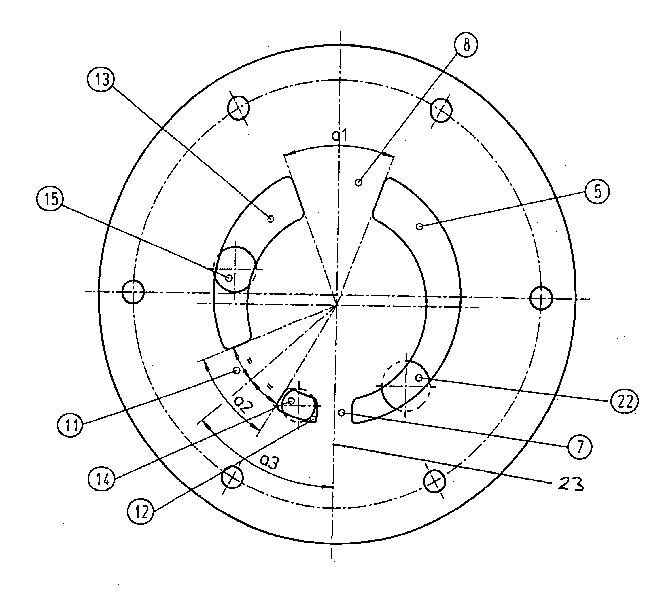
[0014] In the preferred embodiment of the invention, a dummy suction slit and a dummy pressure slit are incorporated into the pump cover, are located opposite the suction slit and the pressure slit, and have the same geometry as these [‘real’ slits]. The two dummy slits prohibit axial forces from affecting the gear system.
[0033] In some applications (double-clutch transmissions), the volume stream of the high pressure chamber is required only for a short period of time when changing gears. It would be a great advantage to divert, unpressurized, the volume stream of the high pressure chamber (approx. 30-40 bar), during the times it is not required, into the suction area and reconnect it when changing gears by means of a bypass [system]. In addition it would be an advantage to raise the volume stream of the high pressure chamber for the short term when changing gears. This would markedly shorten the shift cycle. By use of a variable sealing web 11, this would be cost efficiently possible. These procedures markedly reduce the rated input of the pump.

Problems solved by technology

For example, camshaft adjusters are controlled by a lubrication pump, which, due to the limited pressure level in limited conditions, cannot ensure the function of the camshaft adjuster, because the pressure level of the lubrication pump is too low.
Due to this, there are large losses of efficiency because of the pumps.
For motor lubrication, cost-efficient tandem pumps are employed, which are constructed with two sets of gears and two pump housing halves, whereby one pump-half is shutdown via a bypass to adjust these pumps at a certain pressure and volume stream level whereby a corresponding loss of efficiency occurs.

Method used


Image

  • Double or multiple pump
  • Double or multiple pump
  • Double or multiple pump

Examples


Embodiment Construction

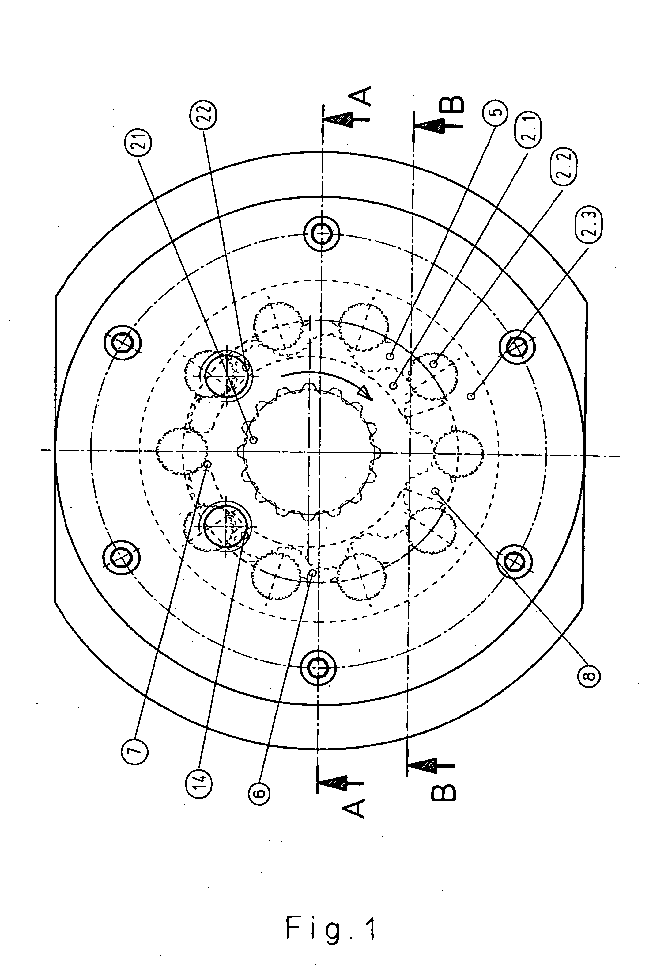
[0045]FIG. 1 shows a pre-fabricated pump housing in which a planetary gear set 2 is eccentrically located. The function of the interlocking gear set is that a drive torque affects and turns the inner rotor 2.1 in the direction of the arrow via a drive shaft 21. Whereby the power is transferred from the toothed inner rotor 2.1 to the planetary gear 2.2. This power creates, on the one hand, a percussive force through the center of the planetary gear and also a tangential force. The tangential force affects a drive torque of the planetary gear 2.2, whereby the percussive force, which affects the bearing ring 2.3 and shifts this bearing ring in rotation.

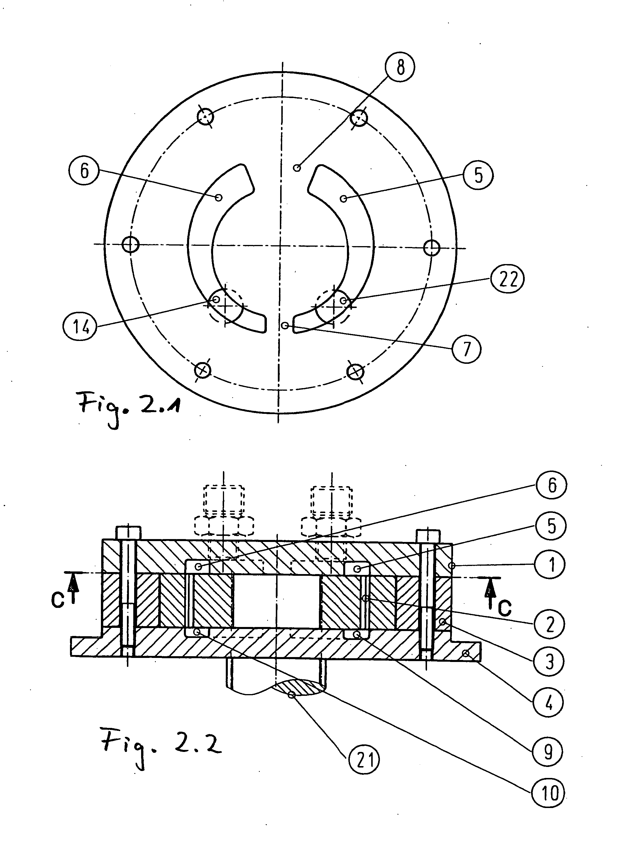
[0046]FIG. 2.1 shows a cross-section along the line C-C from FIG. 2.2 through the pre-fabricated pump housing, according to the state of the art concerning the suction and pressure slits as well as the sealing webs. The pump cover 1 shows the recessed suction slit 5 and the recessed pressure slit 6, both incorporated [in the pump cover]...


PUM


Abstract

Disclosed is a pump for generating at least two volume flows having a different pressure. Said pump comprises a pump cover, a pump housing, and a wheel set that is eccentrically mounted therein. The pump housing is provided with a suction slot and a pressure slot which are separated from each other by means of a first sealing web and a second sealing sew that is located opposite therefrom. The pressure slot is subdivided into a high pressure chamber and a low pressure chamber with the air of at least one additional sealing web, each pressure chamber being provided with a delivery port.

Description

CROSS-REFERNCE TO RELATED APPLICATIONS [0001] This is a continuation of application number PCT / EP2004 / 012222 filed Oct. 28, 2004, which claims priority to German application number 103 50 632.2-15 filed Oct. 29, 2003, the entireties of each is incorporated herein by reference.BACKGROUND OF THE INVENTION [0002] The invention concerns a pump for generating at least two volume streams, in particular, a lubrication pump for internal combustion engines, drive pump and a pump for comparable applications. [0003] Numerous lubrication pumps are known from the state of the art. These pumps deliver a relatively low maximum pressure level with a maximum of 7 to 8 bar. It has been demonstrated in many areas of application in the automobile industry—for camshaft adjusters, motor lubrication, and transmissions, for example—that pumps are required, which are cost-efficient and optimally constructed. [0004] For example, camshaft adjusters are controlled by a lubrication pump, which, due to the limit...

Claims


Application Information

Patent Timeline
Patent Type & Authority Applications(United States)
IPC IPC(8): F01C1/02F04C2/10F04C14/02F04C14/06F04C14/12F04C14/26
CPCF04C2/10F04C14/065F16H57/0434F04C14/26F04C14/12
Inventor BACHMANN, JOSEFSCHWARZE, ROLF
Owner GKN SINTER METALS GMBH & CO KG
Learn More