Integrated simulation system

Inactive Publication Date: 2006-12-14
HITACHI LTD
View PDF2 Cites 21 Cited by
  • Summary
  • Abstract
  • Description
  • Claims
  • Application Information

AI Technical Summary

Benefits of technology

[0024] (6) Within the integrated simulation system as was mentioned above, there may be applied a software simulator for simulating software embedded into equipment, a mechanical-system simulator for simulating a mechanical apparatus, which is driven and controlled by said software, and an electrical-system simulator for simulating an electrical system, which converts data transmitted between said software simulator and said mechanical-system simulator. In such the case, since the target being actually controlled and operated by the software is the hardware, which is built up with the actual electricalal system and the actual mechanical system, it is desired to improve accuracy of a simulation model, comparing between the simulation results, with using simulation models of the electrical system and the mechanical system, and debug and result of verification obtained with using an actual machine therein. For dealing with this, the integrated simulation system as described in the above may have the structure, wherein each of the mechanical-system simulator and the electrical-system simulator has a switching means, for switching over if it individually accesses an actual machine to the co

Problems solved by technology

However, since the product operates in combination with the software, the electrical system and the mechanical system, in one body, or as a unit thereof, therefore it does not operate normally, if even one of them does not operate normally.
However, if starting the debug and verification of the software after completion of those samples of the electrical system and the mechanical system, a term for developing the product extends too long, and there must be prepared the samples in a large number thereof.
For example, the mechanical simulator operates upon only an actuator input(s), but it does not grasp on which kind of operation instruction data is outputted by the software simulator.
However, with any one of such the methods mentioned above, there are many cases where there is the difference in the simulation time thereof, among the software simulator, the electrical-system simulator and the mechanical-system simulator.
However, in the case where the objects of the simu

Method used


Image

  • Integrated simulation system
  • Integrated simulation system
  • Integrated simulation system

Examples


Example

[0051] Hereinafter, embodiments according to the present invention will be fully explained by referring to the attached drawings.

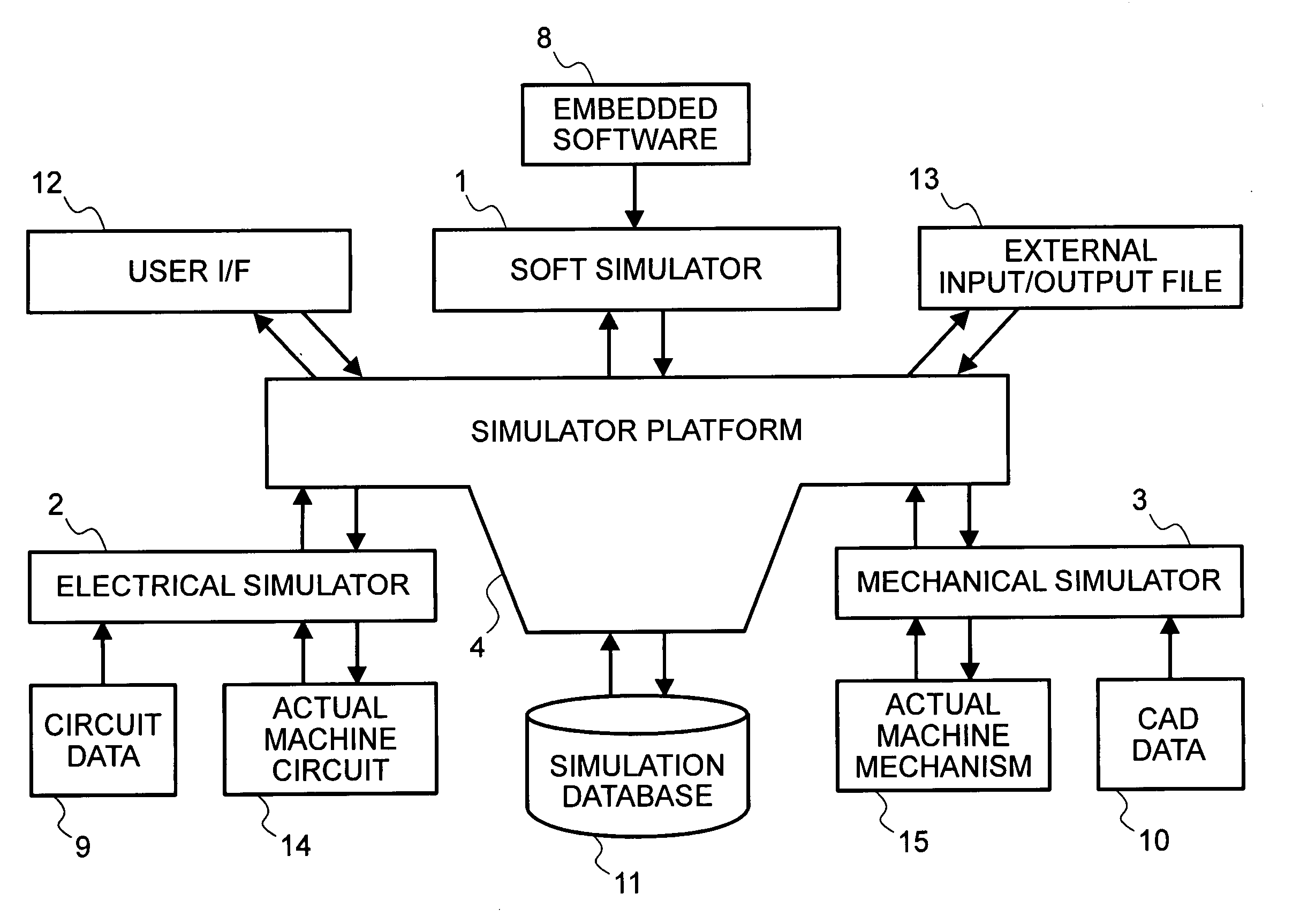
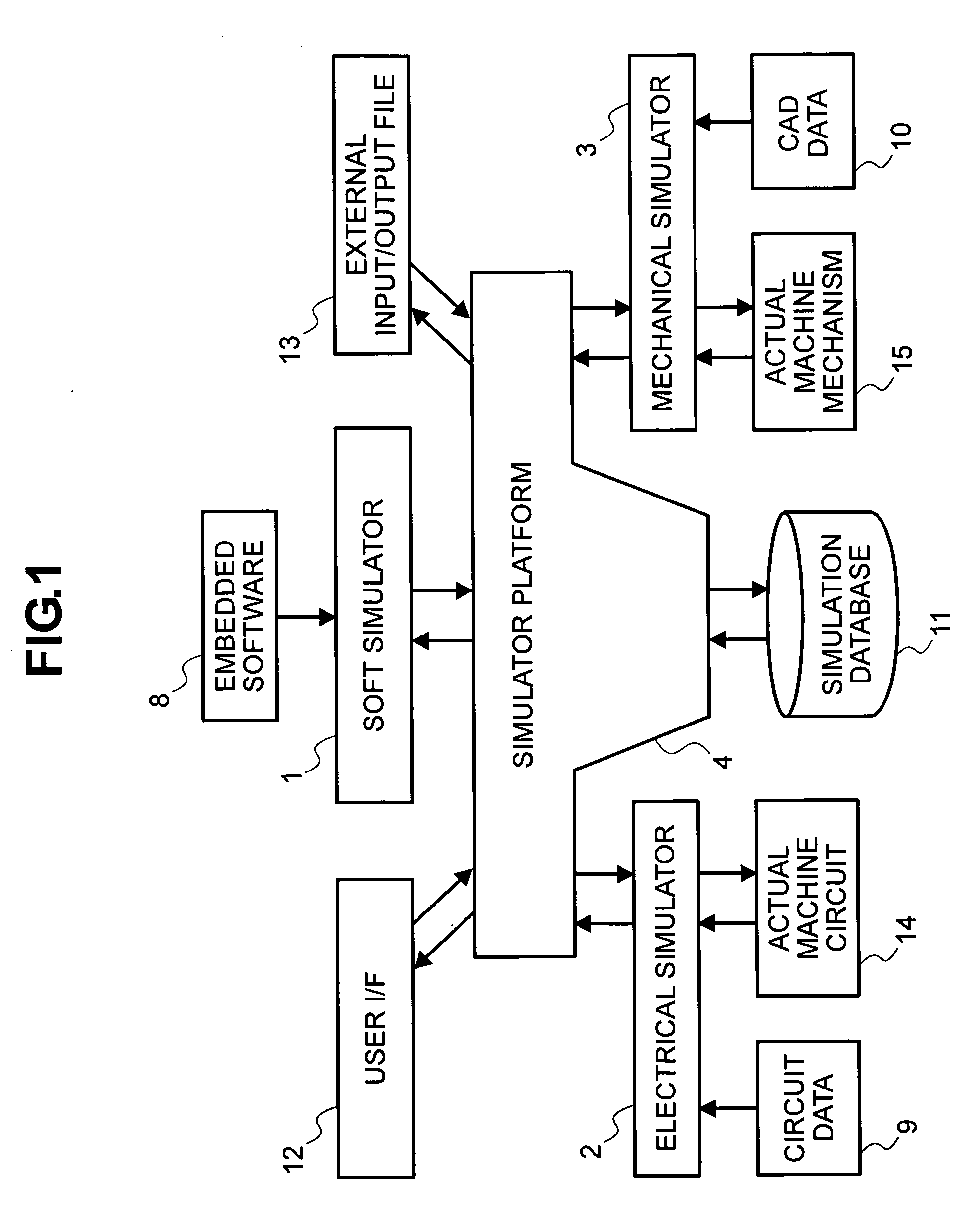
[0052]FIG. 1 shows the basic structures of an integrated simulation system, according to an embodiment of the present invention. The present embodiment, as shown in FIG. 1, relates to a system for executing simulation upon a product, having mechanical parts to be driven and controlled through an electrical system, such as, electric / electronic circuits, etc., with an aid of embedded software installed therein, in corporation with a software simulator 1, an electrical-system simulator 2 and a mechanical-system simulator 3, each being independent from one another. The software simulator 1, the electrical-system simulator (or, a mechanical simulator) 3 are connected with a simulator platform (hereinafter, being called only by a “platform”) 4.

[0053] The platform 4 makes up a corporation means for unifying or integrating the respective simulators; i.e., the so...


PUM


Abstract

An integrated simulation system, for integrally simulating a simulation target having a plural number of elements therein, comprises: simulators, each being provided, independently, for each of the elements, for simulating those elements, respectively; and a corporation means having a common data area for connecting the plural number of simulators accessible thereto. The corporation means has a time management means for managing simulation time, when a synchronization request is issued from anyone of those simulators.

Description

BACKGROUND OF THE INVENTION [0001] The present invention relates to an integrated simulation system, and in particular, it relates to a simulation system being suitable for assisting design and development of a product, including embedded software therein, for example. [0002] In the deign and development of a mechanical system, as an assembly of mechanical parts, which are driven and controlled through an electrical system, such as, electric / electronic circuits, for example, with an aid of embedded software installed therein, the mechanical system and the electrical system are designed, independently, with using the respective tools for exclusive use thereof. [0003] However, since the product operates in combination with the software, the electrical system and the mechanical system, in one body, or as a unit thereof, therefore it does not operate normally, if even one of them does not operate normally. Confirmation and / or verification must be done upon the operation under the condit...

Claims


Application Information

Patent Timeline
IPC IPC(8): G06F17/50G06F11/28G06F19/00
CPCG06F17/5009G06F30/20
Inventor KAGEYAMA, KEIJINISHIGAKI, ICHIROSASAKI, YASUOMATSUNAGA, MITSUOONODERA, MAKOTOKATAOKA, ICHIROTOKISUE, HIROMITSU
Owner HITACHI LTD
Why Eureka
Try Eureka