Digital TV receiving device

a technology for receiving devices and tvs, applied in the field of digital video receiving technology, can solve problems such as limit and inconvenience to the work environment of users, poor reception of conventional analog systems at the viewing end, and connection of priors

Inactive Publication Date: 2006-12-14
ELITEGROUP COMPUTER SYSTEMS
View PDF7 Cites 8 Cited by
  • Summary
  • Abstract
  • Description
  • Claims
  • Application Information

AI Technical Summary

Benefits of technology

[0007] The primary purpose of the present invention is to provide a digital TV receiving device that does not requi

Problems solved by technology

Furthermore, inter terms of signal transmission, conventional analog system is vulnerable to poor reception at the viewing end due to interference by terrain and man-made surface features.
However,

Method used


Image

  • Digital TV receiving device
  • Digital TV receiving device
  • Digital TV receiving device

Examples


Embodiment Construction

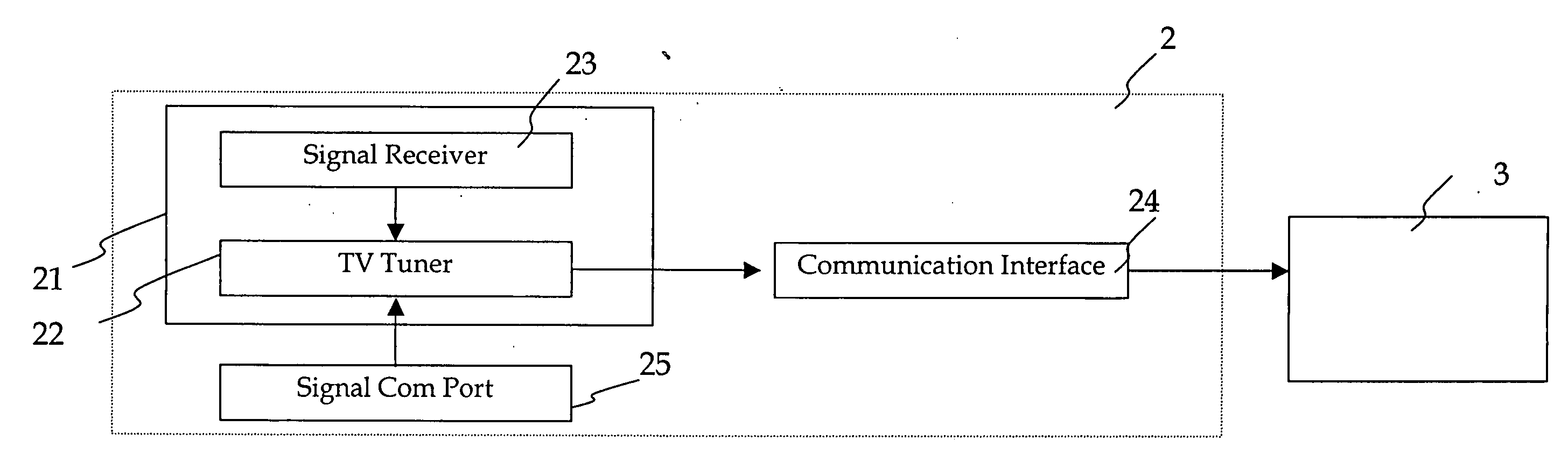
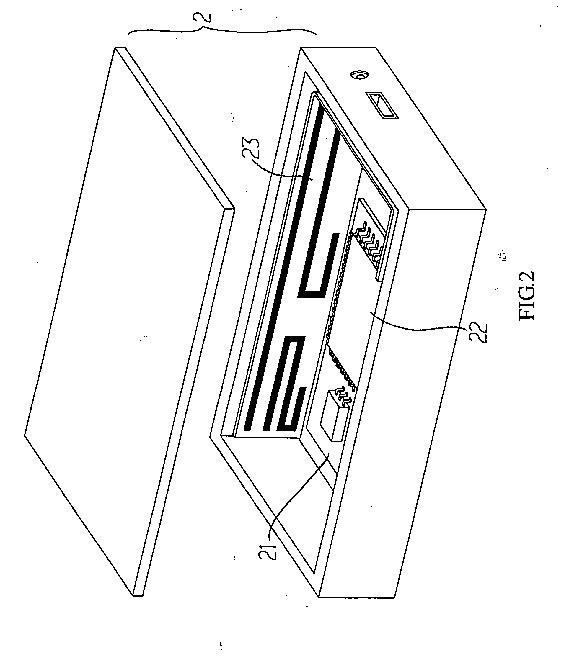
[0019] The digital TV receiving device of the present invention is made in a box type externally connected to a monitor as illustrated in FIG. 2 or in a circuit board adapted in the monitor as illustrated in FIG. 3. In either form, a digital TV receiving device 2 of the present invention is essentially comprised of a control circuit board 21 and a TV tuner 22. A signal receiver 23 directly printed on a micro-ban antenna as illustrated in FIG. 2 on a flexible circuit board or on a flat antenna as illustrated in FIG. 3 of the control circuit board 21.

[0020] The signal receiver 23 receives signals transmitted form a digital TV broadcasting system and the TV tuner 22 decodes / modulates those signals received. In the preferred embodiment, the TV tuner 22 relates to the comparatively popular Advanced Television System Committee(ATSC, USA specifications), Digital Video Broadcast-Terrestrial(DVB-T, European specifications), Digital Video Broadcast-Cable(DVB-C) or Digital Video Broadcast-Han...


PUM


Abstract

A digital TV receiving device includes a control circuit board and a TV tuner; a built-in signal receiver in the digital TV receiving device receives AV signals transmitted by digital TV broadcasting system; the TV turner decodes and modulates those AV signals, and then transmits modulated/restored digital signals to an externally connected information host to output for presentation.

Description

BACKGROUND OF THE INVENTION [0001] (a) Field of the Invention [0002] The present invention is related to a digital video receiving technology at the viewing end of a digital video system, and more particularly, to a digital television(TV) receiving device provided with built-in signal receiver that can be adapted to an information host (e.g., flat panel computer, notebook or desktop computer). [0003] (b) Description of the Prior Art [0004] Digital video broadcasting for providing top picture quality, top sound quality, and value-added service derived from digital broadcasting is taking over the conventional analog system. Furthermore, inter terms of signal transmission, conventional analog system is vulnerable to poor reception at the viewing end due to interference by terrain and man-made surface features. On the contrary, signals from digital video broadcasting system transmitted via cable, satellite, microwave, and ground media provides better and more programs at the viewing end...

Claims


Application Information

Patent Timeline
IPC IPC(8): H04N7/18H04N7/173G06F3/00G06F13/00H04N5/50H04N9/475H04N5/445H04N5/44
CPCH01Q1/12H01Q1/22H01Q1/2266H01Q1/2275H01Q1/36H04N21/43632H04N5/4401H04N5/765H04N5/907H04N21/4113H04N21/41407H01Q1/38H04N21/426
Inventor LIN, MING-YEANG
Owner ELITEGROUP COMPUTER SYSTEMS
Why Eureka
Try Eureka