Mold split insert

a technology of inserts and split inserts, applied in glass shaping apparatus, glass blowing apparatus, food shaping, etc., can solve the problems of complicated and costly manufacturing, cooling time of molds, etc., and achieve the effect of simple and more economical manufacturing and reducing the problem of sink marks

Inactive Publication Date: 2006-12-21
HUSKY INJECTION MOLDING SYST LTD
View PDF10 Cites 26 Cited by
  • Summary
  • Abstract
  • Description
  • Claims
  • Application Information

AI Technical Summary

Benefits of technology

[0017] In particular, the mold split insert of the present invention includes a coolant channel configuration for providing homogenous cooling of the molding surface, and hence mitigating the problem of sink marks in the molded article, and that is also relatively simple and more economical to manufacture.

Problems solved by technology

However, with increasingly aggressive molding cycles, and the resultant reductions in mold cooling time, a temperature gradient may be imparted around the molding surface that can be a source of certain defects in the molded preform.
While the foregoing examples of neck ring inserts include a coolant channel configuration that may mitigate the problem of inhomogeneous cooling around the molding surface, they are also complicated and costly to manufacture.

Method used


Image

  • Mold split insert
  • Mold split insert
  • Mold split insert

Examples


Embodiment Construction

)

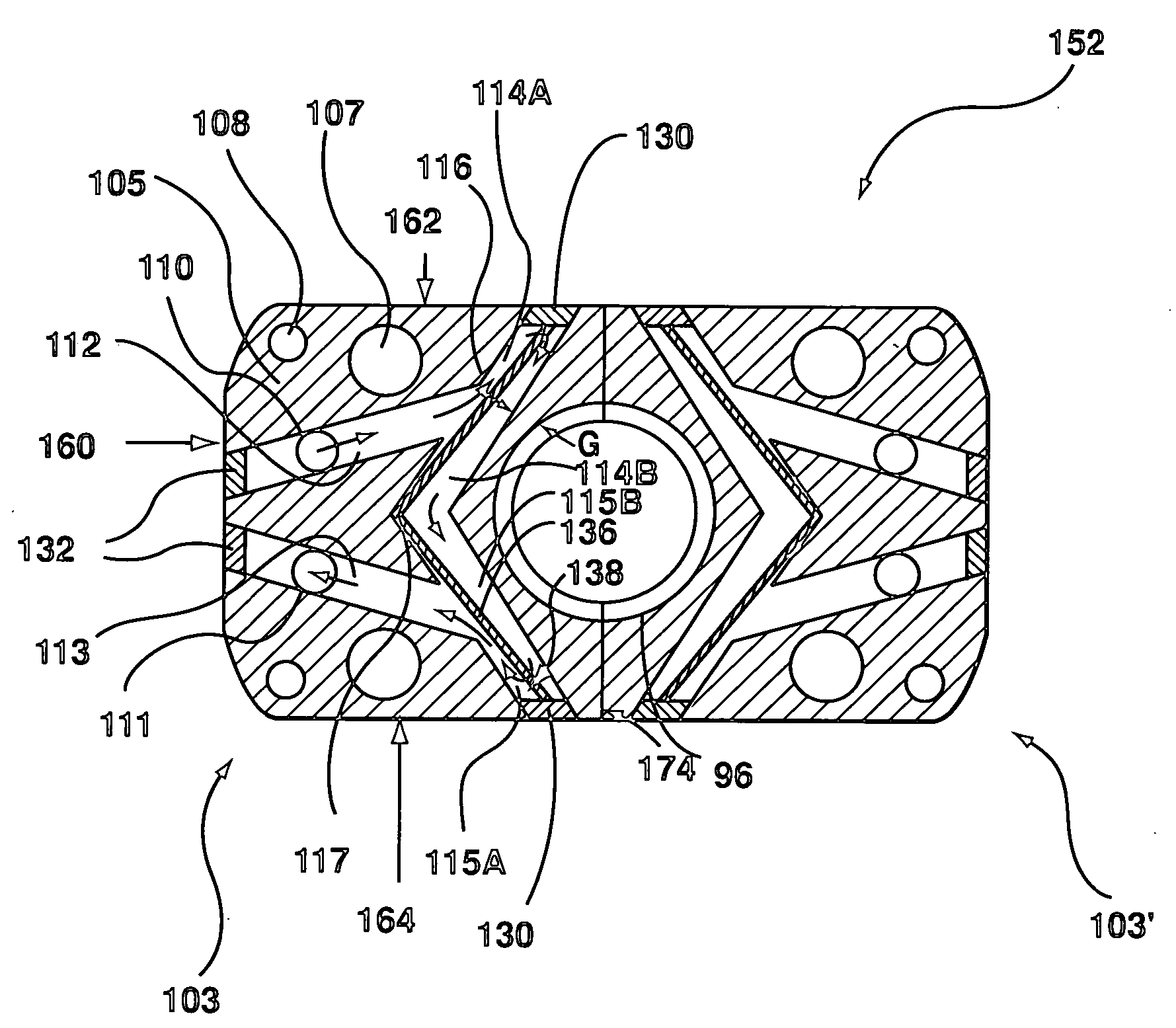
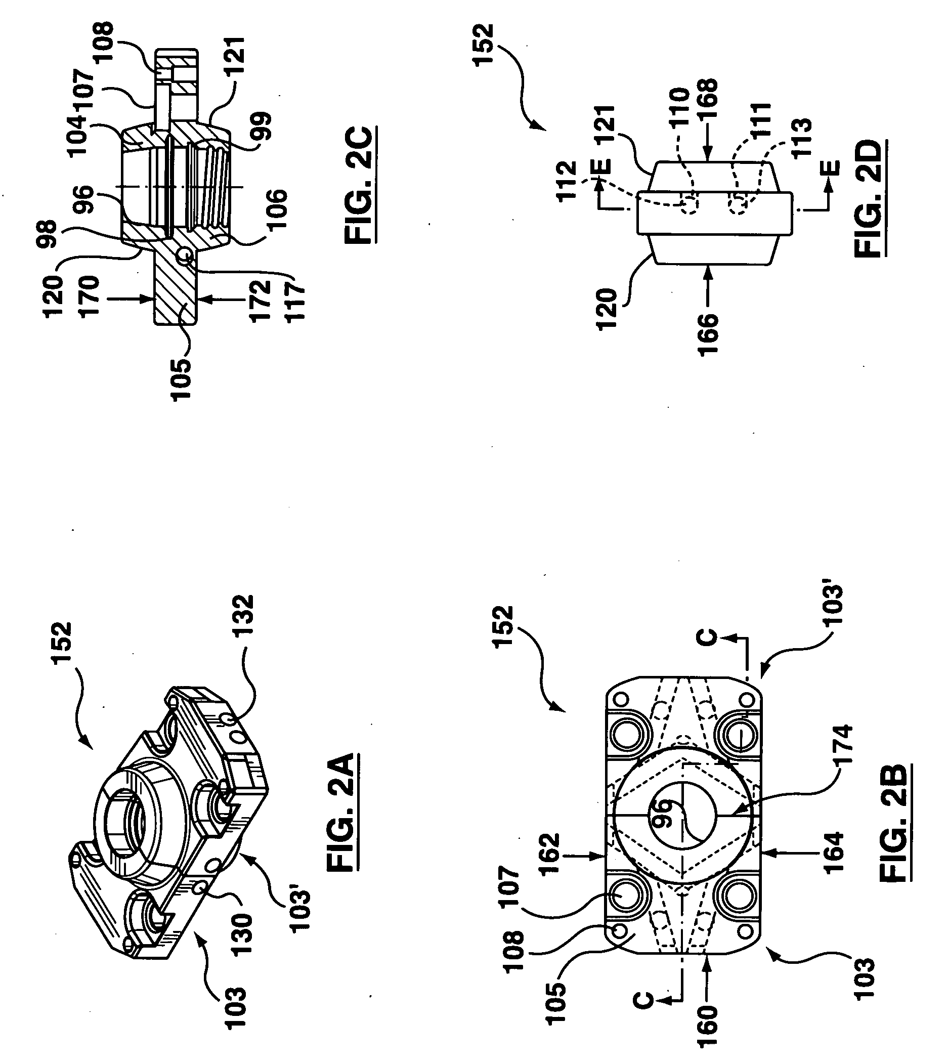
[0032] In accordance with a first embodiment of the present invention, a mold split insert pair is shown with reference to FIG. 2A that is configured for use as a preform mold neck ring insert pair 152 for molding a neck portion of a preform (not shown). The neck ring insert pair 152 comprises a pair of complementary neck ring inserts 103, 103′. As the complementary neck ring inserts 103, 103′ of the embodiment of the invention are to be similarly configured, as with the alternative embodiments that follow, only the neck ring insert 103 will be described in detail.

[0033] As further shown with reference to FIGS. 2B & 2C, the neck ring insert 103 is preferably formed from an integral body that includes an upper and a lower projecting portions 104, 106 that extend from a top and a bottom face 170, 172 of a flange portion 105, respectively. Without specific limitation, the flange portion 105 is preferably configured to have a generally rectangular shape, and the upper and lower projec...


PUM

PropertyMeasurementUnit
moldingaaaaaaaaaa
thickaaaaaaaaaa
interfaceaaaaaaaaaa

Abstract

A mold split insert for use in a molding stack assembly, and in particular a preform mold neck ring insert for use in an injection molding stack assembly for making bottle mold preforms. The split insert comprises a body with a molding surface configured thereon. The split insert also includes a coolant channel configured in the body with a partition arranged therein. The partition dividing a portion of the coolant channel into a first and a second branch. A transfer coolant channel is configured between the branches.

Description

TECHNICAL FIELD [0001] The present invention relates, in general, to a mold split insert for use in a molding stack assembly and is particularly, but not exclusively, applicable to a preform mold neck ring insert that is configured for molding an outer surface of a neck portion of a plastic preform, or parison, of the type that may be blow molded into a bottle. More particularly, the present invention relates to the use of a partition in a coolant channel of the split insert for configuring a coolant flow between the ends of an effective coolant channel that extends substantially peripherally around a portion of a molding surface disposed thereon. BACKGROUND OF THE INVENTION [0002] As commonly known, a mold split insert is used in a complementary pair thereof for molding portions (e.g. threads, lugs, rings, and other laterally projecting features) of a molded article that would otherwise be entrapped therein. In particular, a portion of the molding surface is split, usually in half,...

Claims


Application Information

Patent Timeline
Patent Type & Authority Applications(United States)
IPC IPC(8): C03B9/44C03B9/38C03B11/00C03B9/04
CPCB29C33/04B29C45/33B29K2105/253B29C2033/042B29C2045/7264B29C45/7312B29C45/26B29C33/12B29C45/73
Inventor DUBUIS, DAVIDTRUSGNACHDUARTE, MARCO
Owner HUSKY INJECTION MOLDING SYST LTD
Why Eureka
Try Eureka