
Method for a surface rewind system

a rewinding machine and surface technology, applied in the direction of web handling, thin material processing, transportation and packaging, etc., can solve the problems of non-uniform wind profile of typical non-uniformly wound products, unstable logs, and non-uniform product wind profil

Active Publication Date: 2006-12-21
THE PROCTER & GAMBLE COMPANY
View PDF14 Cites 9 Cited by
  • Summary
  • Abstract
  • Description
  • Claims
  • Application Information

AI Technical Summary

Problems solved by technology

Even though certain of these exemplary surface rewind machines are commercially available, those of skill in the art have realized that these machines have certain drawbacks.
Primary among these drawbacks is the fact that product produced from these exemplary rewind systems are known to have non-uniform wind profiles.
A typical non-uniformly wound product generally exhibits a non-uniform wind profile by having visually observable tight and loose portions in the wound roll.
Additionally, certain of the exemplary surface rewind systems can cause logs to become unstable during the winding of low-density wound rolls.
Such log instability can limit the speed of the rewinder as well as the rewinder throughput capability.
This complexity adds a high degree of uncertainty in the ability to provide a process that produces a uniformly wound product.
Thus, it should be clear that these current surface rewinder control methods are non-theoretically based and cause non-uniformly wound rolls.
This approach can be particularly problematic when winding low-density products having large diameters with little total wound paper length.

Method used


Image

  • Method for a surface rewind system
  • Method for a surface rewind system
  • Method for a surface rewind system

Examples


Embodiment Construction

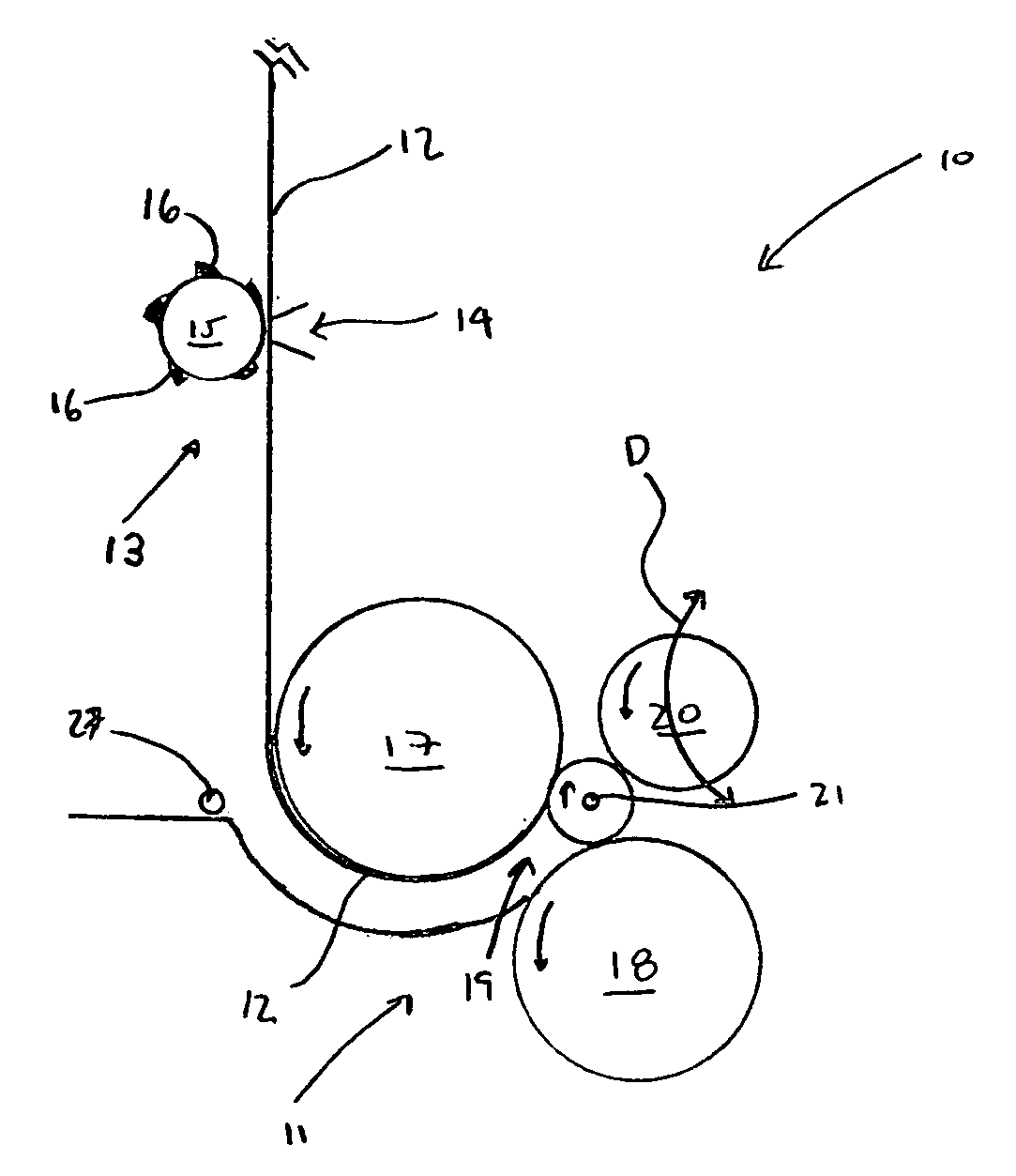
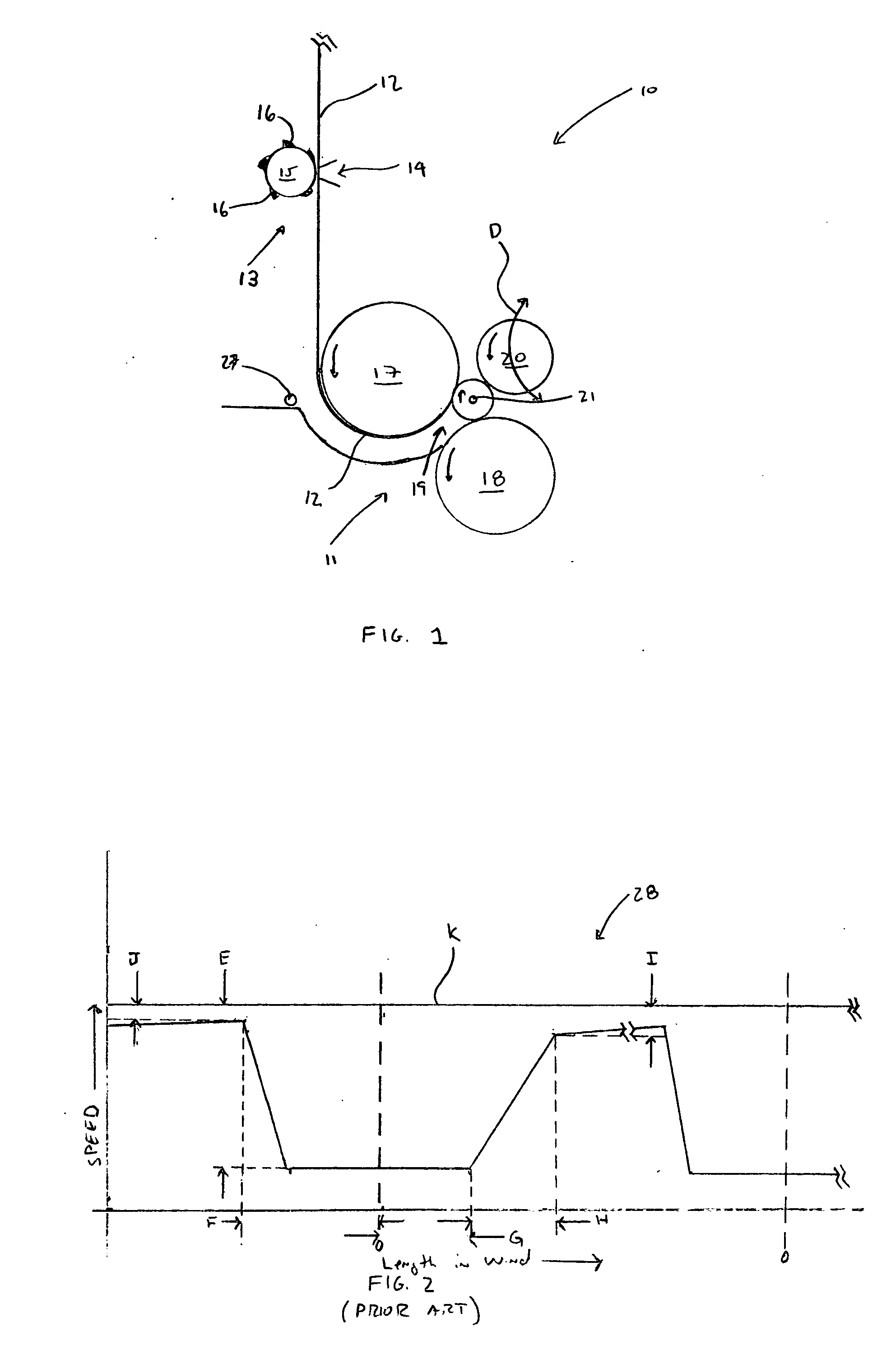
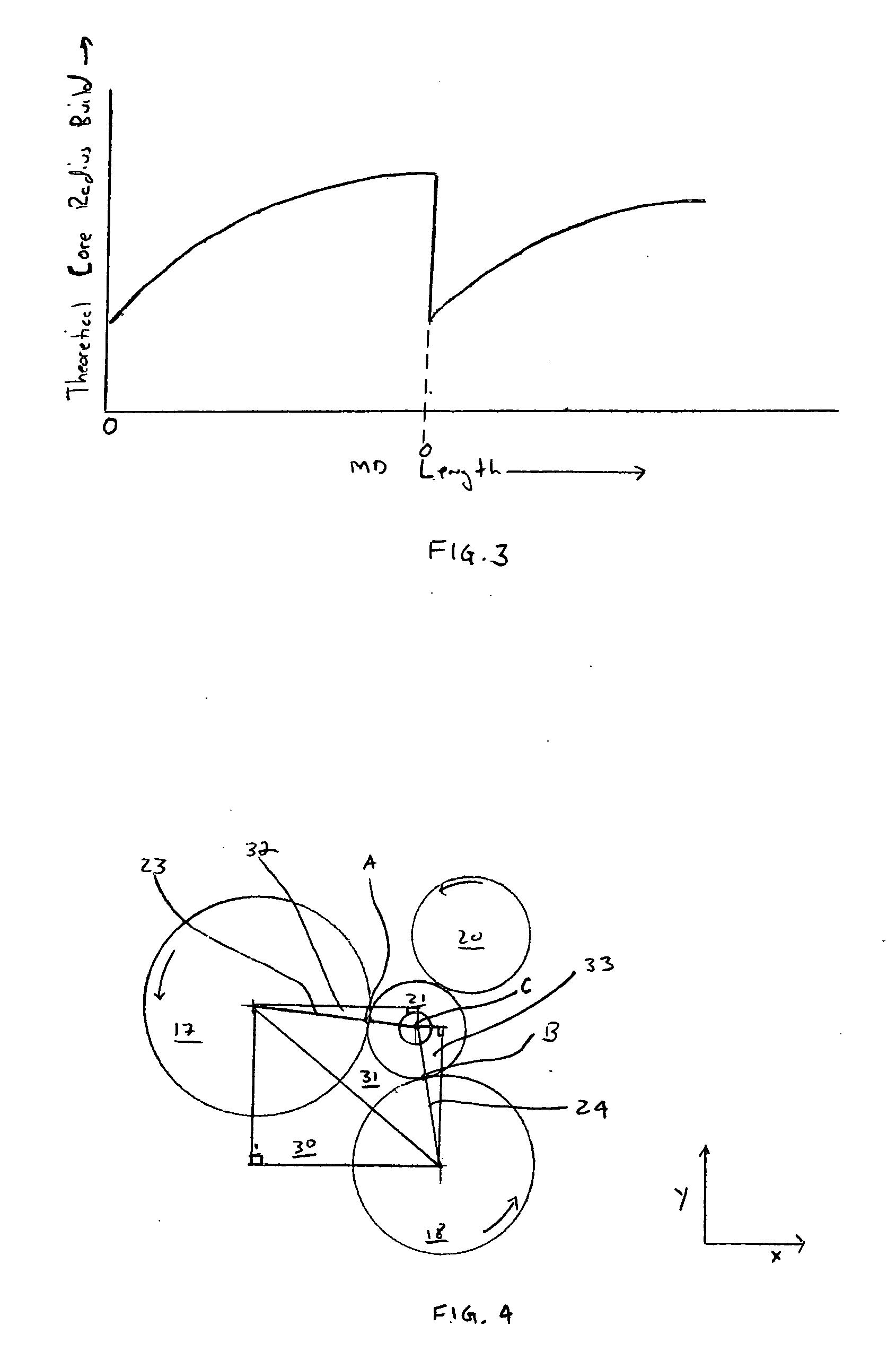
[0019]FIG. 1 depicts the basic elements of a surface rewinding machine 10 (also referred to herein as surface rewinder 10 or rewinder 10). A web material 12 is fed from a supply parent roll (not shown) to the winding region 11 of the rewinder 10. Virtually any known process upstream of winding region 11 could process the web material 12. Such processes may include, but not be limited to, embossing, lotioning, coating, printing, combining of two or more web materials, combinations thereof, and the like. Generally, the web material 12 is fed through a perforation assembly 13. As is known to one of skill in the art, a perforation assembly 13 can be provided with a non-rotating support 14 and a rotating perforation roller 15 having blades 16 disposed thereon. As would also be known to one of skill in the art, the non-rotating support 14 can be provided with a blade (not shown) which is cooperatively associated with blades 16 disposed upon rotating perforation roller 15 to provide a line...


PUM


Abstract

A theoretical based winding process and control for a surface winding machine that can provide the capability to wind products with a desired wind profile, uniform sheet compression, improved compressibility, winding stability, and ease of operator control adjustment, is disclosed herein. The theoretical based surface winding process utilizes the principle of winding a log with a desired wind profile by controlling the surface speed of at least one roller of the surface winding machine.

Description

FIELD OF THE INVENTION [0001] The present invention is directed to an improved method for operating and controlling a surface rewinding machine. This includes a method for the formation of logs or rolls of web material wound on a central core. BACKGROUND OF THE INVENTION [0002] As known to those skilled in the art, a surface rewinder is generally used for producing smaller diameter logs, or rolls, of web material wound upon a central core from large diameter parent rolls. Typically, these machines are used in the paper converting industry to produce rolls of bath tissue, kitchen towels, all purpose wipes, and the like. It is known that formed logs of web material may be as long as 510 centimeters and have an outer diameter of about 10 to 15 centimeters. The formed logs of web material are then subsequently cut transversely to their axis to obtain small rolls of wound web material that may have a length ranging from 10 to 30 centimeters in length. [0003] Several types of surface rewi...

Claims


Application Information

Patent Timeline
IPC IPC(8): B65H18/20
CPCB65H23/1813
Inventor DOOLEY, MATTHEW DANIELSCHWAMBERGER, BRIAN CHRISTOPHER
Owner THE PROCTER & GAMBLE COMPANY
Learn More