Sub-frame of vehicle

a subframe and vehicle technology, applied in the direction of roofs, transportation and packaging, vehicle arrangements, etc., can solve the problems of time and labor for joining the divided blocks, the inability to make a large frame body by means of casting being restricted by an existing casting apparatus, etc., to achieve the degree of freedom of the joining portion can be advantageously enhanced, and the degree of freedom of welding enhanced

Inactive Publication Date: 2006-12-21
HONDA MOTOR CO LTD
View PDF13 Cites 95 Cited by
  • Summary
  • Abstract
  • Description
  • Claims
  • Application Information

AI Technical Summary

Benefits of technology

[0019] According to the invention described in aspects 1 and 6, the sub-frame made by die casting is constituted in such a manner that the right and left rear beam members are joined to the right and left front beam members of the front sub-frame, and the flat portions are formed in the right and the left front beam members or the right and the left rear beam members so that the flat portions can be start points of plastic deformation when a load, which is heavier than a normal load, is given to the flat portions in the longitudinal direction. Therefore, when the mechanical strength of the right

Problems solved by technology

However, in the case of the hollow frame (sub-frame) 201 for vehicle use described in Patent Document 1, when a size of the frame body 202 made of an aluminum alloy casting is ex

Method used


Image

  • Sub-frame of vehicle
  • Sub-frame of vehicle
  • Sub-frame of vehicle

Examples


Embodiment Construction

[0035] Referring to the accompanying drawings, the best mode for carrying out the invention will be explained below.

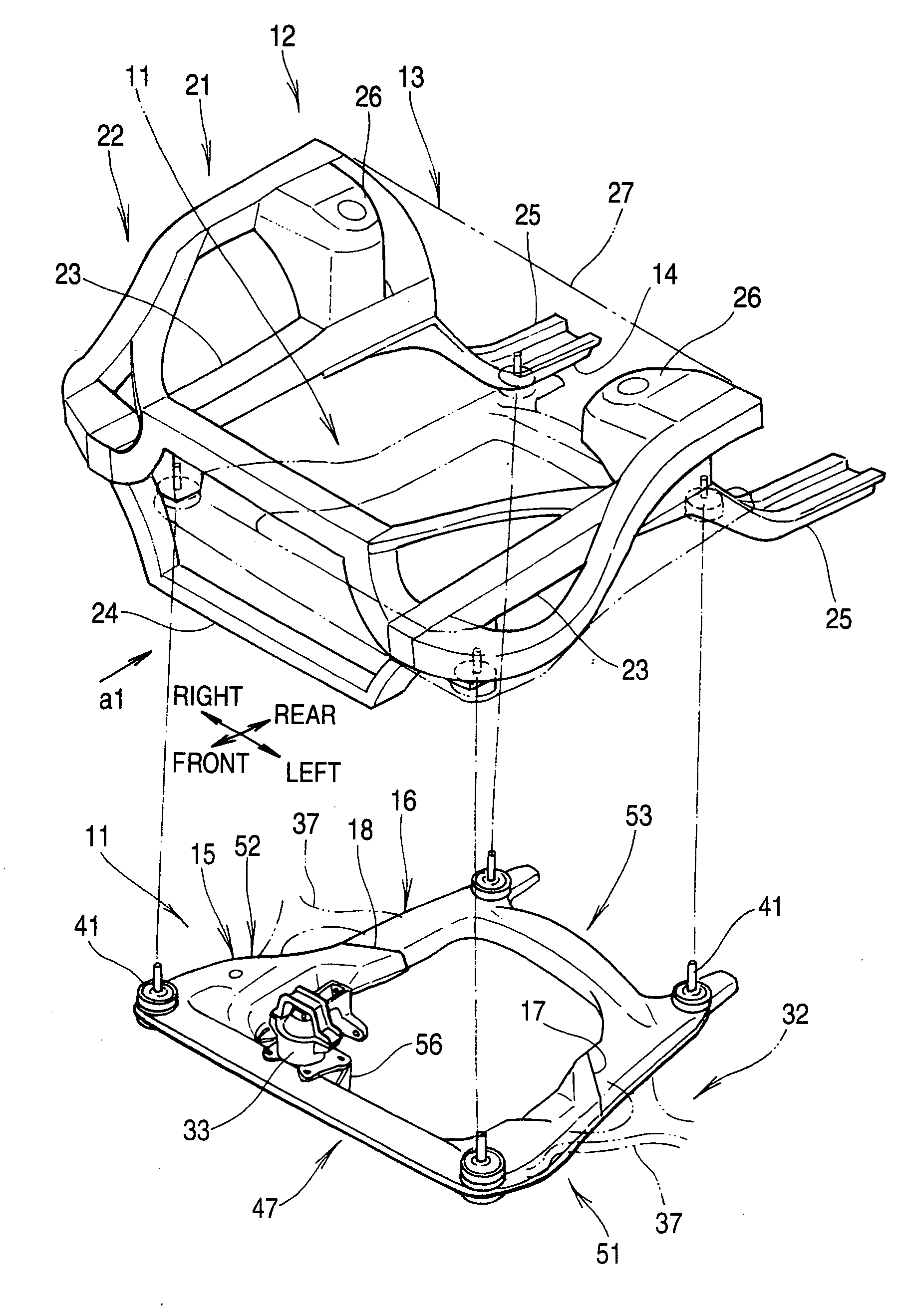
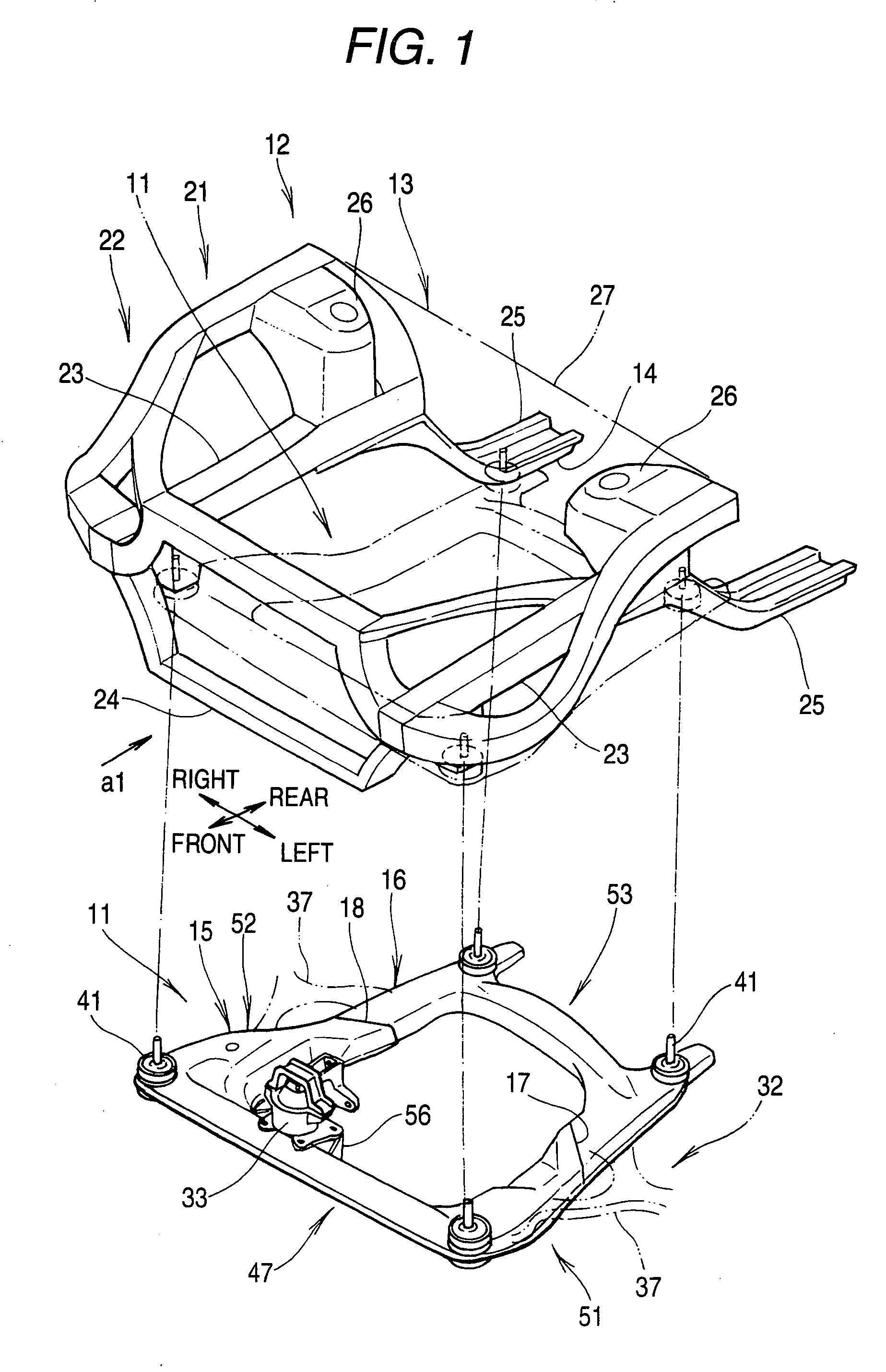
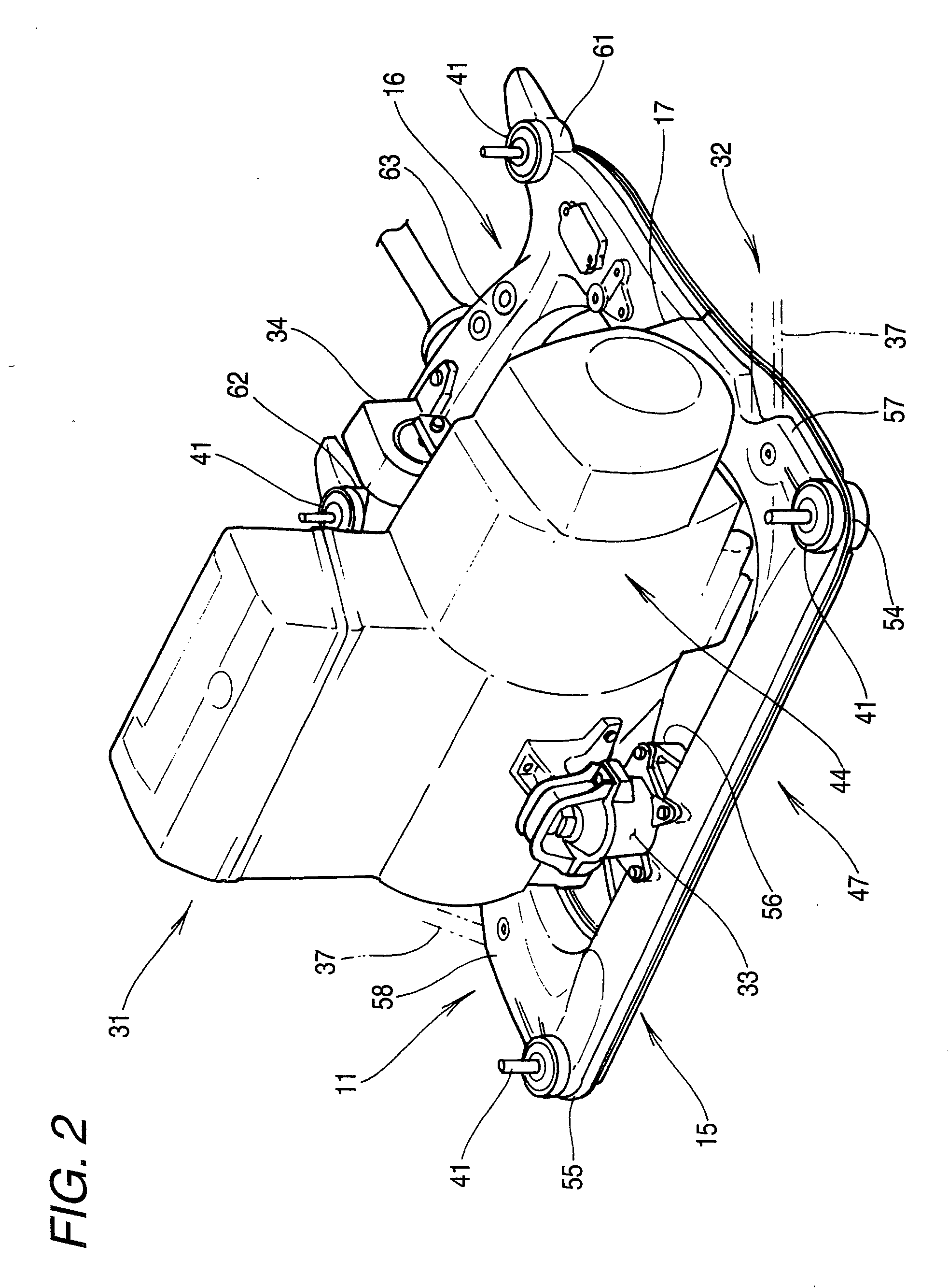
[0036]FIG. 1 is a schematic illustration for explaining an outline of a sub-frame of a vehicle of the present invention.

[0037] The sub-frame 11 is attached, for example, to a lower portion 14 of a vehicle body 13 of a vehicle 12. The sub-frame 11 includes: a front sub-frame 15; and a rear sub-frame 16, that is, the sub-frame 11 is constituted being divided into two blocks. The thus divided blocks are joined to each other by the right and left joining portions 18, 17. This structure of the sub-frame 11 will be specifically described later.

[0038] The vehicle body 13 is provided with a front body 22 which is a front portion 21.

[0039] In this case, the front body 22 is used for an FF vehicle. The front body 22 includes: a right and a left front side member 23, 23; a front cross member 24 joined to forward end portions of the front side members 23, 23; floor members 25,...


PUM


Abstract

A sub-frame 11 of a vehicle, which is made by means of die casting into a substantially rectangular shape and attached to a front lower portion 14 of a vehicle body 13, includes: a C-shaped front sub-frame 15; and a C-shaped rear sub-frame 16, wherein a right and a left front beam members 65, 67, which are formed at a right and a left end portion of a front beam member 47 constituting the front sub-frame 15, and a right and a left beam rear members 96, 97, which are formed at a right and a left end portion of a rear beam member 53 constituting the rear sub-frame 16, are joined to each other, and flat portions 113, 114 are formed in the right and the left front beam members 65, 67 so that the flat portions can be start points of plastic deformation of the sub-frame 11 when a load, which is heavier than a normal load, is given to the sub-frame 11 in the longitudinal direction.

Description

BACKGROUND OF THE INVENTION [0001] The present invention relates to a substantially rectangular sub-frame of a vehicle attached to a front lower portion of a vehicle body. [0002] Concerning the substantially rectangular sub-frame made by means of die casting, a hollow frame for vehicle use and a vehicle are well known. For example, refer to Patent Document 1. [Patent Document 1][0003] JP-A-2004-210013 (FIG. 3 on page 11) [0004] Referring to the following drawing, Patent Document 1 will be explained below. [0005]FIG. 13 is a view for explaining a basic structure of a sub-frame of the conventional art (Patent Document 1). A hollow frame (sub-frame) 201 for vehicle use of the conventional art is constituted in such a manner that a lid body 203 made of aluminum alloy is joined to a frame body 202 made of an aluminum alloy casting so as to form a hollow portion. This hollow frame (sub-frame) 201 for vehicle use of the conventional art is advantageous in that the weight is small and it c...

Claims


Application Information

Patent Timeline
IPC IPC(8): B60K37/00
CPCB62D21/11
Inventor MIYAHARA, TETSUYA
Owner HONDA MOTOR CO LTD
Why Eureka
Try Eureka