
Amplifier having half-wave tracking power rails

Inactive Publication Date: 2006-12-21
BROADCOM INT PTE LTD
View PDF4 Cites 35 Cited by
  • Summary
  • Abstract
  • Description
  • Claims
  • Application Information

AI Technical Summary

Benefits of technology

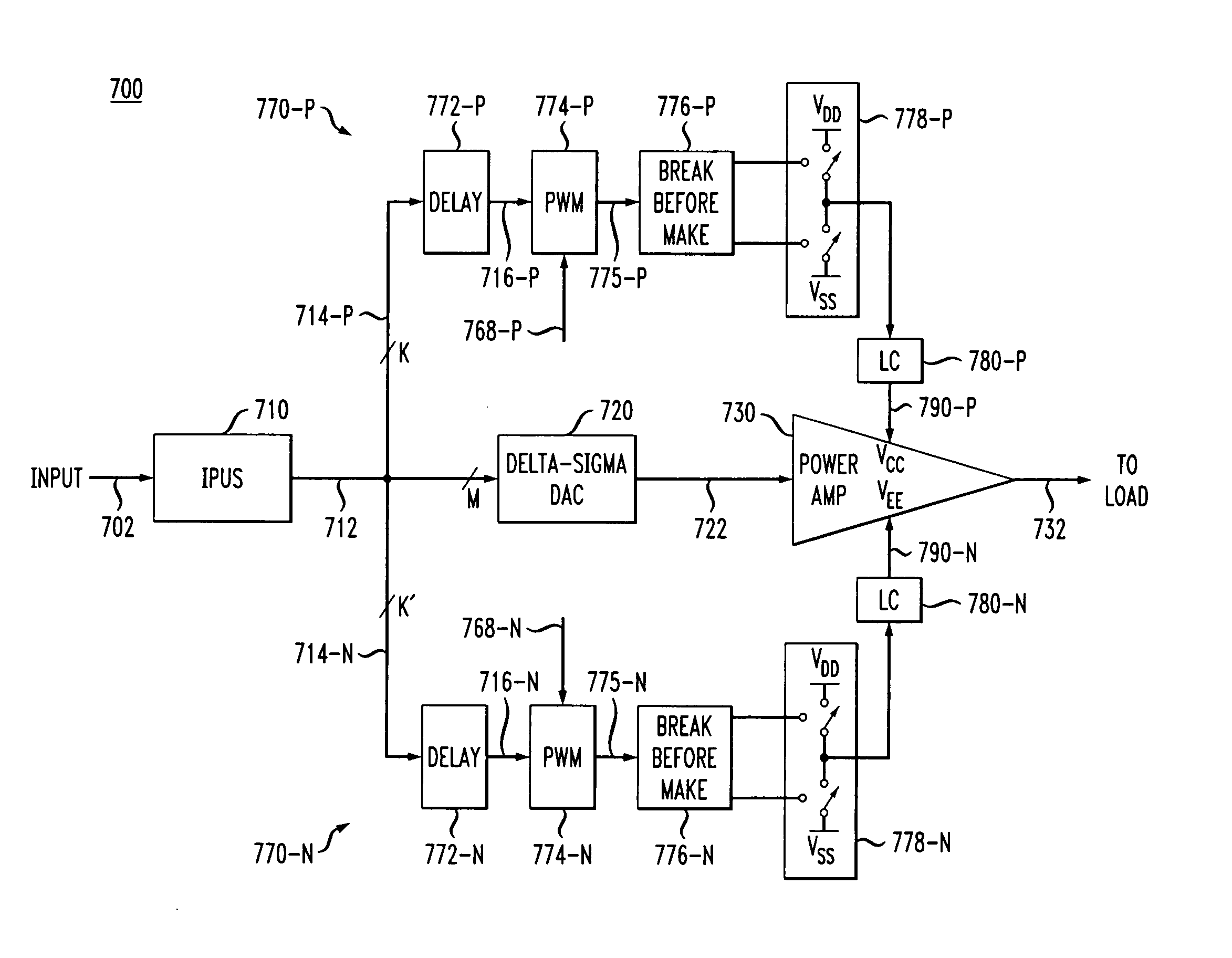
[0012] Problems in the prior art are addressed by various embodiments of an amplifier adapted to generate an analog output signal in response to a digital input signal and having an output stage powered by a power-supply circu

Problems solved by technology

However, the efficiency of Class A amplifiers in converting DC-source power into AC-output power is quite poor because the continuous current flow causes a relatively large portion of the DC-source power to be dissipated as heat.
Less frequently, Class A amplifiers are used in large-signal applications, for which the need for good linearity outweighs the cost and heat disadvantages associated with the poor power efficiency.
However, this efficiency improvement comes at the cost of substantial output waveform distortions.
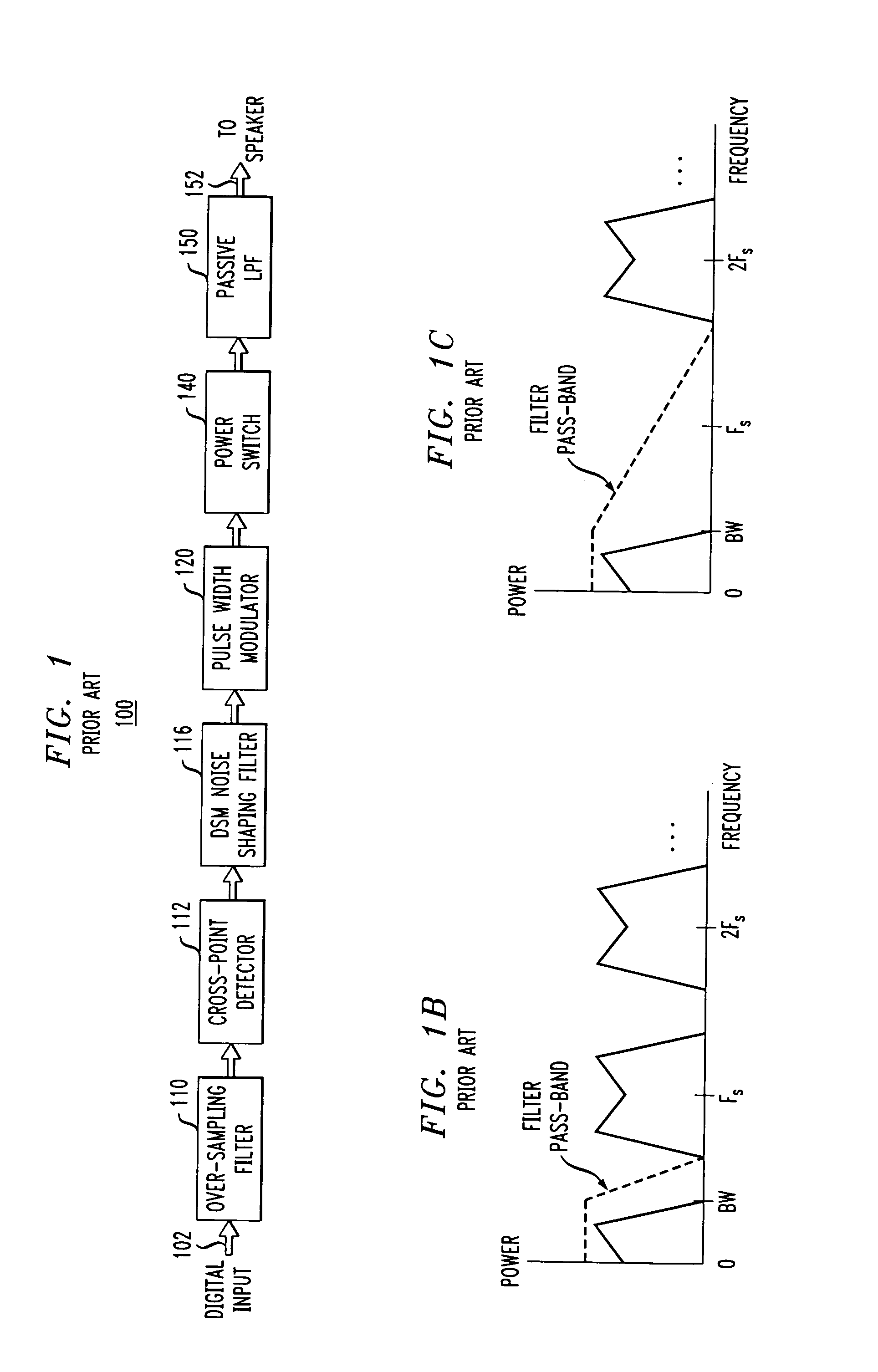
While Class D amplification would be a preferred approach to solving the power efficiency problem, practical implementations of Class D amplifiers suitable for an audio application encounter significant problems.
As a result, any in-band power-supply ripple passes through to the speaker, which can produce an audible noise, and any high-frequency power-supply ripple aliases into the signal band by disturbing comparator thresholds.
In addition, it is often difficult to achieve stable operation of the closed-loop system due to significant nonlinearities in its feed-forward path.
Further problems include (1) difficulties in implementing precision analog signal processing of the mixed analog / digital design in an integrated circuit (IC) environment, especially for a system that handles large voltages and / or currents, and (2) poor compatibility with the deep submicron technology.

Method used


Image

  • Amplifier having half-wave tracking power rails
  • Amplifier having half-wave tracking power rails
  • Amplifier having half-wave tracking power rails

Examples


Embodiment Construction

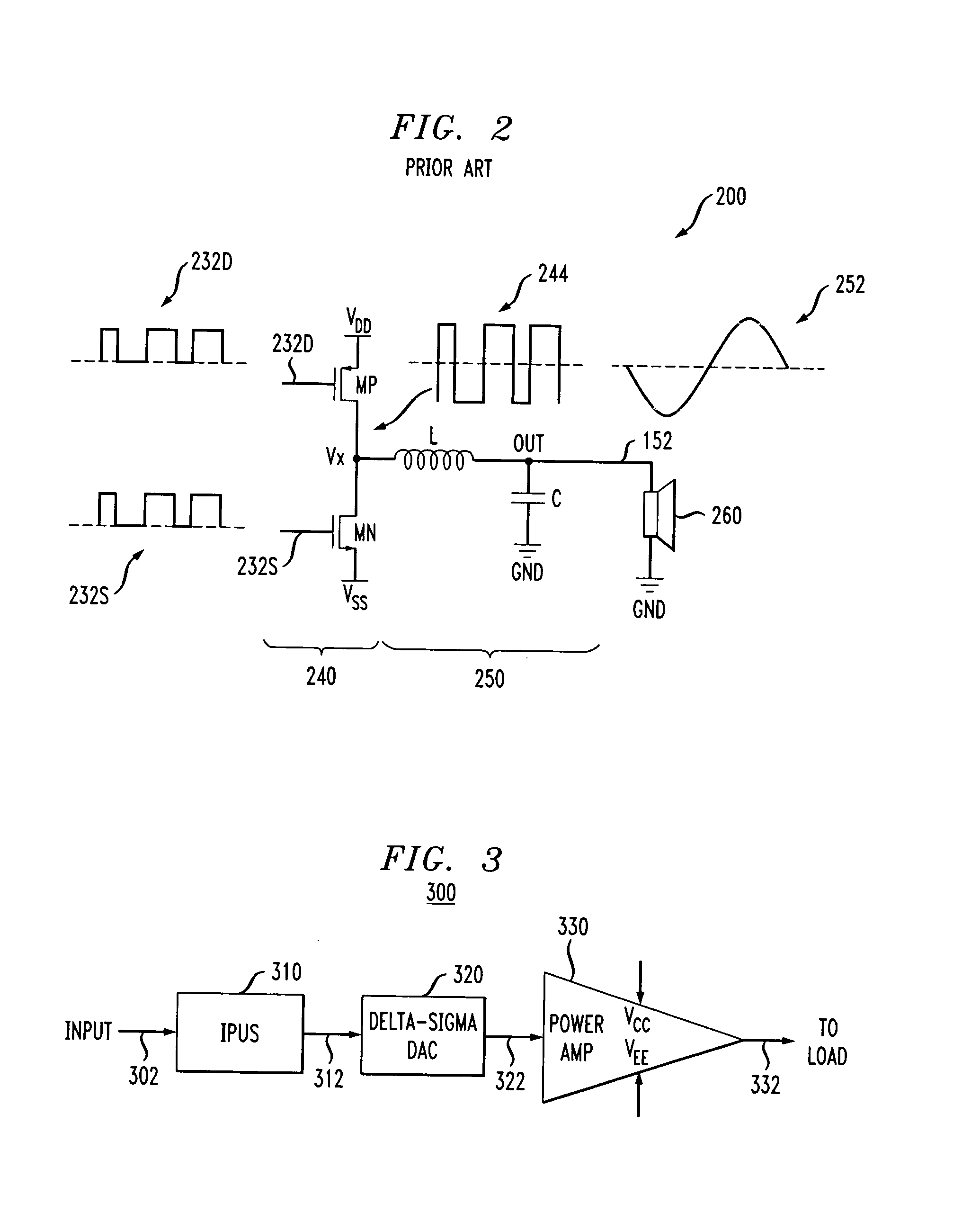
[0027] In one embodiment, an amplifier of the invention is an amplifier comprising a main amplification path and first and second power-supply paths. The main amplification path has (i) an interpolator and up-sampler (IPUS) adapted to process an input signal to generate a corresponding M-bit digital signal, (ii) a digital-to-analog converter adapted to convert the M-bit digital signal into a corresponding analog signal, and (iii) a power amplifier adapted to amplify said analog signal to generate the output signal. The power amplifier is powered by positive and negative power rails generated by the first and second power-supply paths, respectively. Each of the first and second power-supply paths has a digital pulse-width modulator (PWM) adapted to process a K-bit signal carrying the K most-significant bits of the M-bit digital signal, where K<M, and generate the respective sequence of pulses based on that K-bit signal and a digital control signal specifying an offset voltage between...


PUM


Abstract

An amplifier adapted to generate an analog output signal in response to a digital input signal and having an output stage powered by a power-supply circuit, which generates one or more power rails for the output stage such that at least one of these power rails tracks the output signal and substantially represents a biased and half-wave rectified version of that output signal.

Description

CROSS-REFERENCE TO RELATED APPLICATIONS [0001] This application claims priority from U.S. Provisional Patent Application No. 60 / 692,094 filed Jun. 20, 2005, and entitled “Power Amplifier with Half-Tracking Power Rails from Digital PWM D / A Converter,” which is incorporated herein in its entirety.BACKGROUND OF THE INVENTION [0002] 1. Field of the Invention [0003] The present invention generally relates, but is not limited, to audio amplifiers and, more specifically, to Class AB amplifiers. [0004] 2. Description of the Related Art [0005] A typical audio amplifier uses two complementary transistors (or groups of transistors) to drive a speaker. The amplifier might have a first transistor, which conducts current from the positive power-supply voltage to the speaker for the positive portion of the audio waveform, and a second transistor, which conducts current from the negative power-supply voltage to the speaker for the negative portion of the audio waveform. Audio amplifiers are classif...

Claims


Application Information

Patent Timeline
IPC IPC(8): H03F3/38
CPCH03F1/0222H03F3/217H03F2200/331
Inventor PERUZZI, ROBERT O.RICH, DAVID A.
Owner BROADCOM INT PTE LTD
Learn More