Layout configuration of differential signal transmission lines for printed circuit board

Inactive Publication Date: 2006-12-21
HONG FU JIN PRECISION IND (SHENZHEN) CO LTD +1
View PDF4 Cites 15 Cited by
  • Summary
  • Abstract
  • Description
  • Claims
  • Application Information

AI Technical Summary

Problems solved by technology

With the ever increasing speeds of integrated circuits (ICs), signal integrity is becoming one of the most important problems.
Many factors, such as the parameters of the electrical elements or the PCB and the layout of the PCB, can affect the signal integrity, or lead to instability of the syst

Method used


Image

  • Layout configuration of differential signal transmission lines for printed circuit board
  • Layout configuration of differential signal transmission lines for printed circuit board
  • Layout configuration of differential signal transmission lines for printed circuit board

Examples


Embodiment Construction

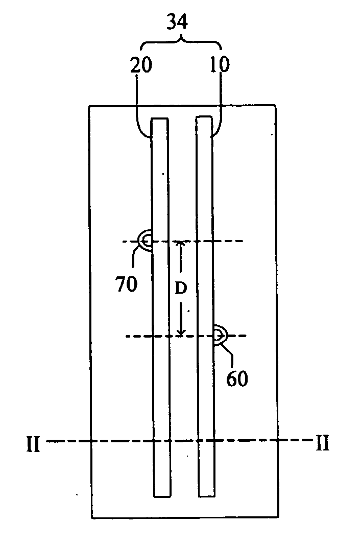
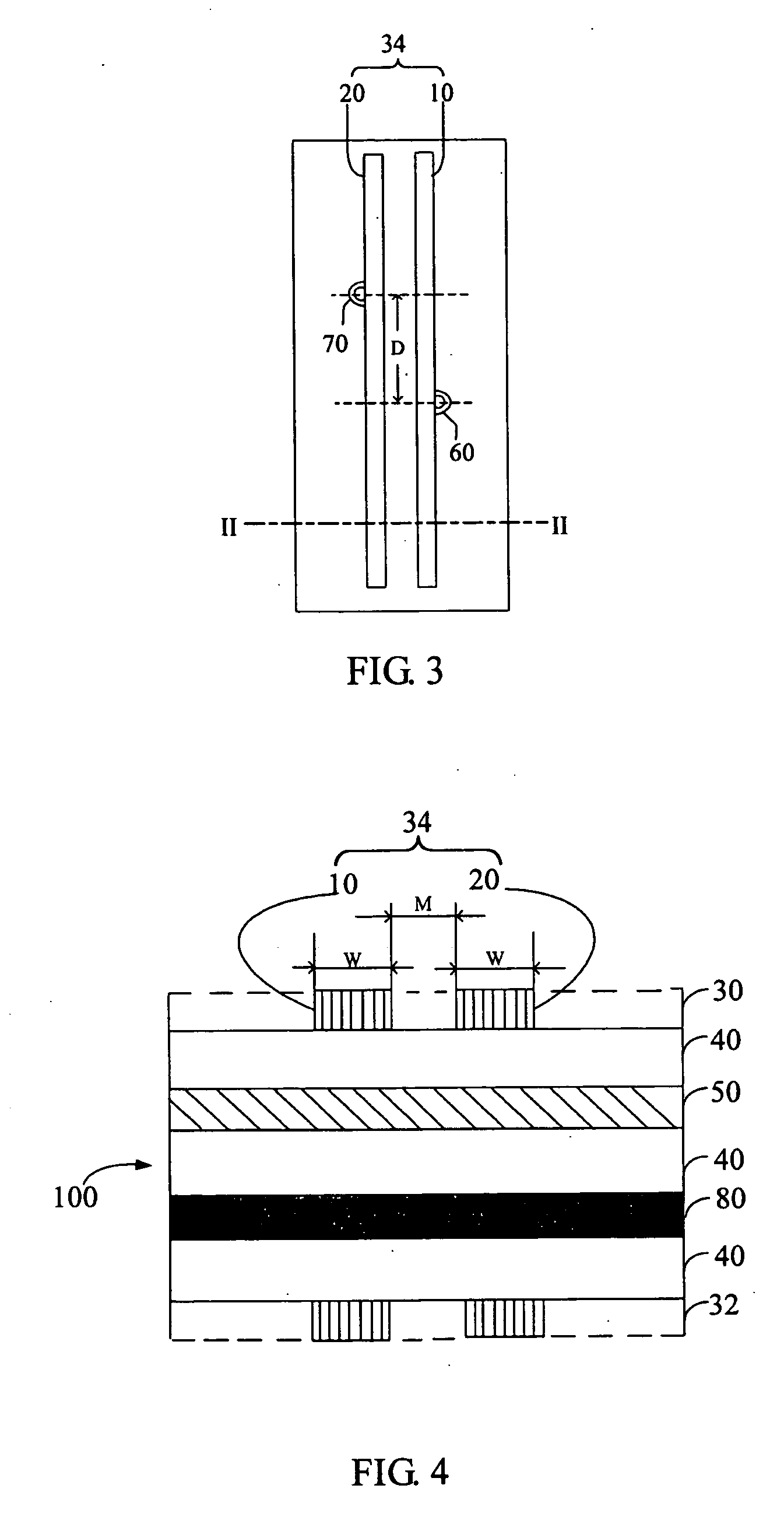
[0019] Referring to FIG. 3 and FIG. 4, a 4-layer PCB 100 includes a first signal plane 31, a medium layer 40, a ground plane 50, another medium layer 40, a power plane 80, another medium layer 40, and a second signal plane 32, in that order. In the first signal plane 31, there is a differential pair 34. The differential pair 34 includes a transmission line 10 and a transmission line 20. The line 10 and the line 20 have a same length, and are parallel. A width M between the line 10 and the line 20 is invariable. A width of the line 1 or the line 2 is W. Discontinuous connective points for the differential pair like a through via 60 abutting the line 10 and another through via 70 abutting the line 20 are dissymmetrical about the differential pair 34. Radiuses of the via 60 and the via 70 are same. A distance between the vias 60, 70 along the differential pair 34 is a length D.

[0020] Referring to FIG. 5 to FIG. 7, using simulation software, such as Computer Simulation Technology (CST)...


PUM


Abstract

A layout configuration of a differential pair for a printed circuit board (PCB) having a signal plane is provided. In a preferred embodiment, the layout configuration comprises: a differential pair on the signal plane; a pair of vias abutting the differential pair, and the pair of vias being mutually dissymmetrical about the differential pair; and a distance between the pair of vias along the differential pair being equal to ½ TV, wherein T is a signal rise time, V is a speed of the signal. Therefore, the layout configuration can meet with the requirements of impedance matching, reduce reflection, and improve signal integrity.

Description

BACKGROUND [0001] 1. Field of the Invention [0002] The present invention relates to a layout configuration of signal transmission lines of a printed circuit board (PCB), and more particularly to a layout configuration of signal transmission lines of a (PCB) with regard to the signal integrity of high-speed signals. [0003] 2. General Background [0004] With the ever increasing speeds of integrated circuits (ICs), signal integrity is becoming one of the most important problems. Many factors, such as the parameters of the electrical elements or the PCB and the layout of the PCB, can affect the signal integrity, or lead to instability of the system, possibly even causing the system to breakdown. Thus, preserving signal integrity has become a key point in the design of a PCB. Impedance matching is an important thing for maintaining signal integrity. When the characteristic impedance of a transmission line does not match the impedance of the load, part of the signal will be reflected at th...

Claims


Application Information

Patent Timeline
IPC IPC(8): H01P5/00
CPCH01P3/081H01P3/088H05K2201/09636H05K1/115H05K2201/09236H05K1/0245
Inventor LIN, YU-HSUYEH, SHANG-TSANGLI, CHUAN-BING
Owner HONG FU JIN PRECISION IND (SHENZHEN) CO LTD
Why Eureka
Try Eureka