Method of homogenizing microvolume liquid and apparatus therefor

Inactive Publication Date: 2006-12-21
FUJIFILM CORP +1
View PDF4 Cites 10 Cited by
  • Summary
  • Abstract
  • Description
  • Claims
  • Application Information

AI Technical Summary

Benefits of technology

[0017] Because the liquid is automatically stirred in the pool due to its own inertia, the liquid is homogenized more quickly and efficiently in comparison with the case where the liquid is simply reciprocated in the nozzle. Especially where the pool is formed to be a substantially spherical liquid drop, the liquid flows actively in the pool, promoting the homogenizing effect. The present invention efficiently stirs the

Problems solved by technology

However, the above mentioned conventional liquid mixing methods have a disadvantage that the liquids left so much on inner w

Method used


Image

  • Method of homogenizing microvolume liquid and apparatus therefor
  • Method of homogenizing microvolume liquid and apparatus therefor
  • Method of homogenizing microvolume liquid and apparatus therefor

Examples


Example

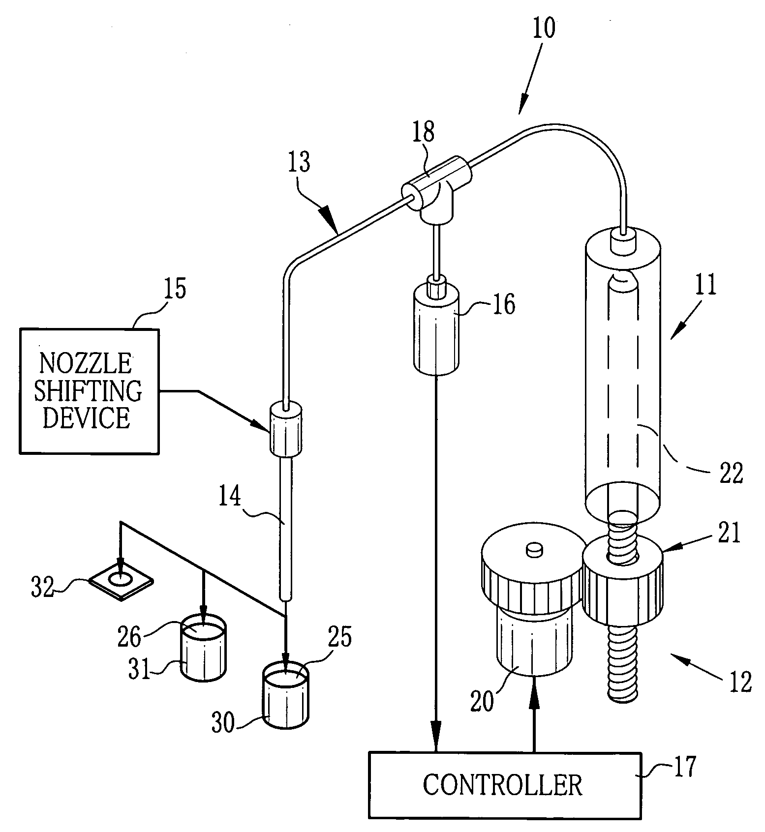
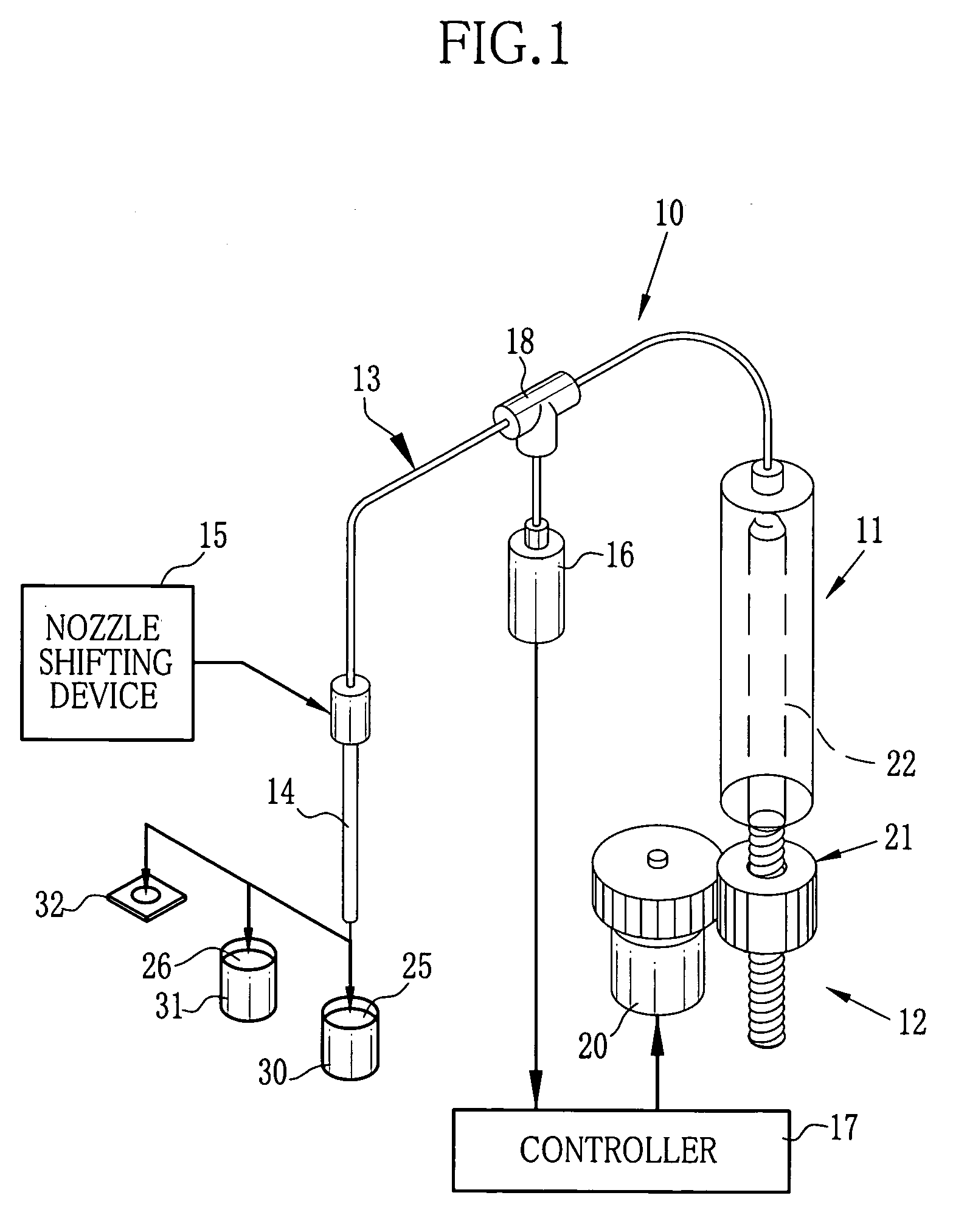
[0026] As FIG. 1 shows, a homogenizer of micro-volume liquids 10 consists of a syringe pump 11 as a liquid sucking discharging mechanism, a pump driver 12, an air tube 13, a suction nozzle 14, a nozzle shifting device 15, a pressure sensor 16 and a controller 17. Based on a signal from the pressure sensor 16, the controller 17 controls every part, to mix micro-volume liquids.

[0027] The suction nozzle 14 is placed with a nozzle end 14a downward and its nozzle top is connected to an end of the air tube 13. The other end of the air tube 13 is connected to the syringe pump 11, which is driven by the pump driver 12. The pump driver 12 consists of a motor 20 and a lead screw mechanism 21, which transforms spins of the motor 20 to reciprocating movements. Rotating the motor 20 forward or backward reciprocates a plunger 22 in the syringe pump 11 and then sucks or discharges liquids 25 and 26 or gas from the suction nozzle 14. The mechanism transforming the rotational movement of the motor ...


PUM

PropertyMeasurementUnit
Diameteraaaaaaaaaa
Volumeaaaaaaaaaa
Inertiaaaaaaaaaaa

Abstract

In a method of homogenizing micro-volume liquid, a first liquid and then a second liquid is sucked into the suction nozzle. The sucked first and second liquids are sent to a nozzle end, to form a pool of a mixed liquid of the first and second liquids at the nozzle end. According to the inertia, the mixed liquid gets so fluid in the pool that the first and second liquids are stirred in the pool. Thereafter, the pool of the mixed liquid is sucked into a liquid channel. According to the kinds of liquids to be mixed, the number of times to form the pool is predetermined. The steps of forming the pool at the nozzle end and sucking it into the liquid channel are repeated by the decided number of times, to homogenize the mixed liquid quickly.

Description

FIELD OF THE INVENTION [0001] The present invention relates to a method of homogenizing micro-volume liquid, and an apparatus for this method. More specifically, the present invention relates to a method of homogenizing micro-volume liquid by forming a pool at an end of a suction nozzle, and an apparatus for this method. BACKGROUND OF THE INVENTION [0002] In conventional automatic analyzers, mixing of different liquids, such as a reagent and a specimen, or a specimen and a diluent, has been done by pouring the different liquids in a reaction cell and then stirring them by a stirring rod. In another mixing method, the different liquids poured in a container are mixed by being repeatedly sucked and discharged into and out of a suction nozzle, as disclosed for example in Japanese Laid-open Patent Application No. Hei 7-239334. A mixing method has also been suggested for example in Japanese Laid-open Patent Application No. 2000-304754, wherein a suction nozzle has different internal diam...

Claims


Application Information

Patent Timeline
IPC IPC(8): B01F5/00
CPCB01F3/0865B01F11/0074B01F11/0071B01F5/02B01F23/451B01F25/20B01F31/651B01F31/65
Inventor SETO, YOSHIHIRO
Owner FUJIFILM CORP
Why Eureka
Try Eureka