
Device for mixing at least two media

a technology of mixing device and media, applied in the direction of rotary stirring mixer, emulsification, transportation and packaging, etc., can solve the problems of uneconomical use of relevant mixing device and waste of expensive base materials

Inactive Publication Date: 2006-12-21
ROBERT BOSCH GMBH
View PDF6 Cites 4 Cited by
  • Summary
  • Abstract
  • Description
  • Claims
  • Application Information

AI Technical Summary

Benefits of technology

[0007] An advantage of an optimum intermixture and a minimization of waste is obtained if a device for mixing at least two media, in particular highly viscous media, having at least one mixing chamber, the volume of which in a mixer housing is variable with the aid of a movable plunger, and having a mixing tool, is designed in such a way that with the aid of an actuator the mixing tool is insertable into the mixing chamber for mixing the media and is retractable from the mixing chamber following the mixing process.
[0008] In a refinement of the present invention of the mixing tool having mixing organs, which are inserted into the mixing chamber only for the actual mixing and are subsequently completely retractable from it, a dead volume during the mixing of the media is avoided. In this manner, an optimum mixing performance is achieved in the device according to the present invention regardless of the media used such that due to the optimum intermixture of the two media nearly the entire supplied quantity has a uniform quality with respect to the mixture.
[0009] Furthermore, by a suitable design of the mixing organs and their passageways through the wall of the mixing chamber, a minimization of waste can be achieved, which arises in known devices especially with highly viscous media such as pastes. Consequently, the device according to the present invention is suitable particularly also for the use of expensive base materials as mixing components such as e.g. platinum, palladium, rhodium, iridium and the like. For this purpose, the device according to the present invention may also take the form of a paste mixing robot.

Problems solved by technology

Furthermore, comparatively large residues remain on the mixing organs such that the use of expensive base materials produces valuable waste, or that the use of the relevant mixing device proves to be uneconomical.

Method used


Image

  • Device for mixing at least two media
  • Device for mixing at least two media
  • Device for mixing at least two media

Examples


Embodiment Construction

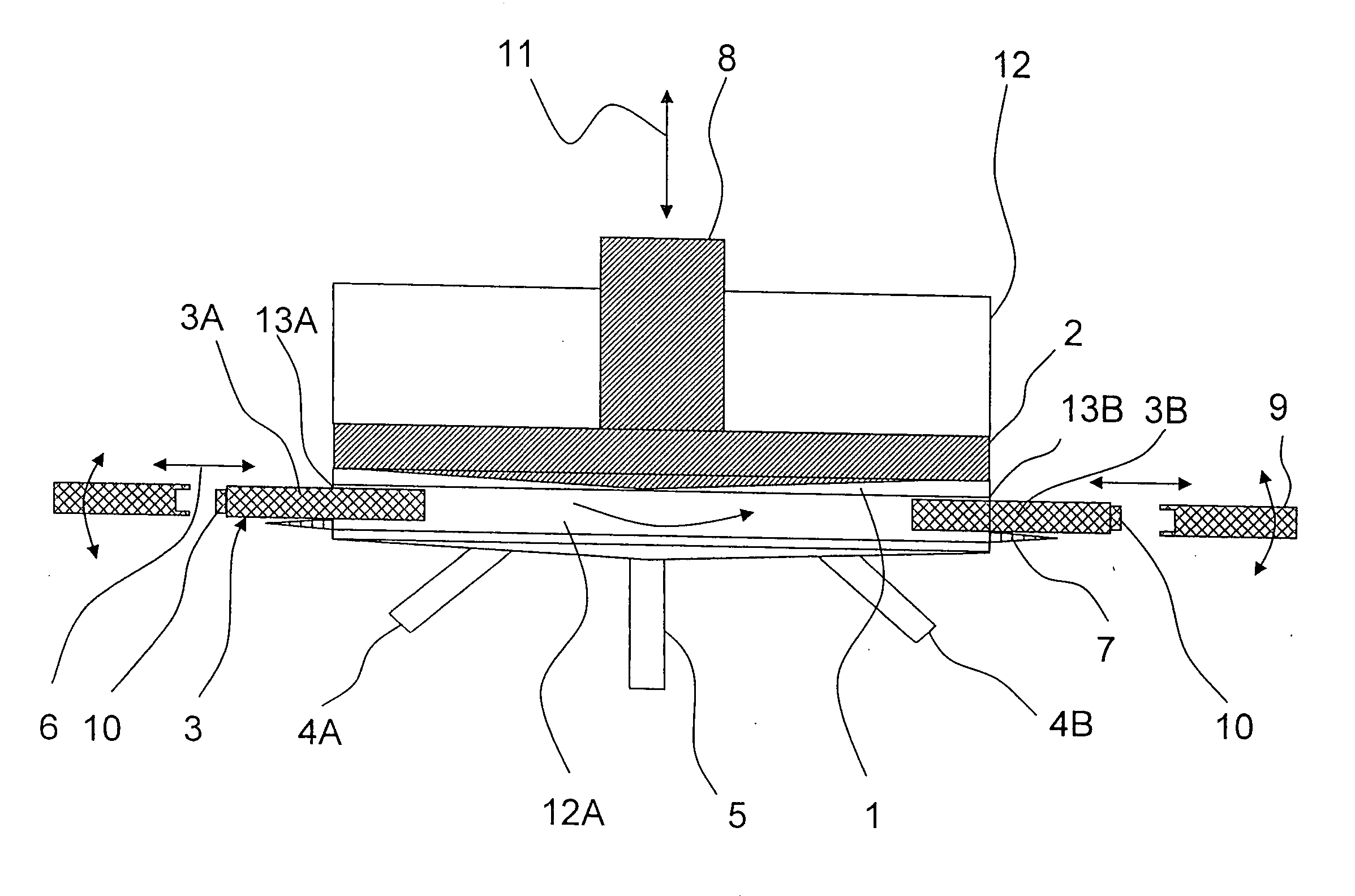
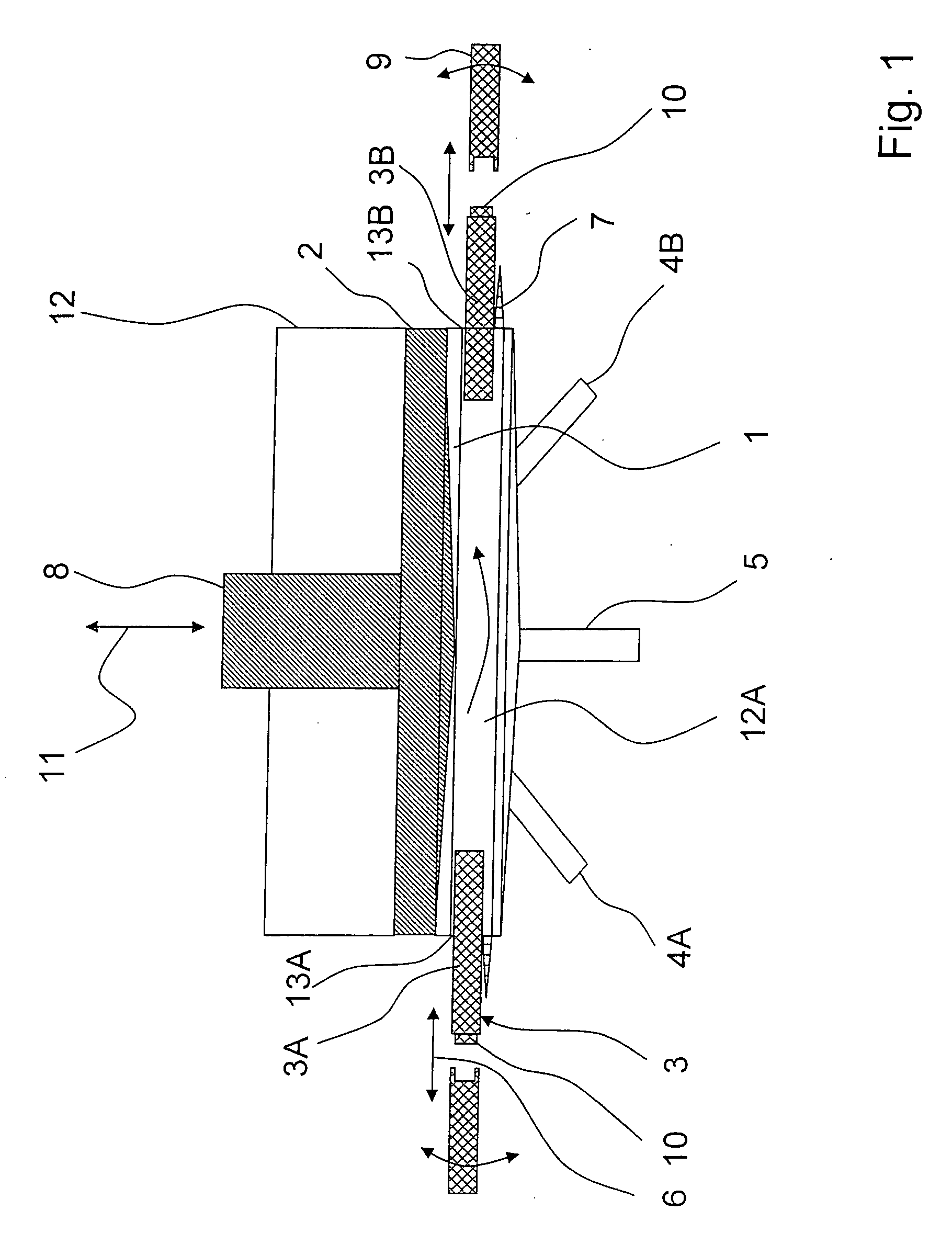
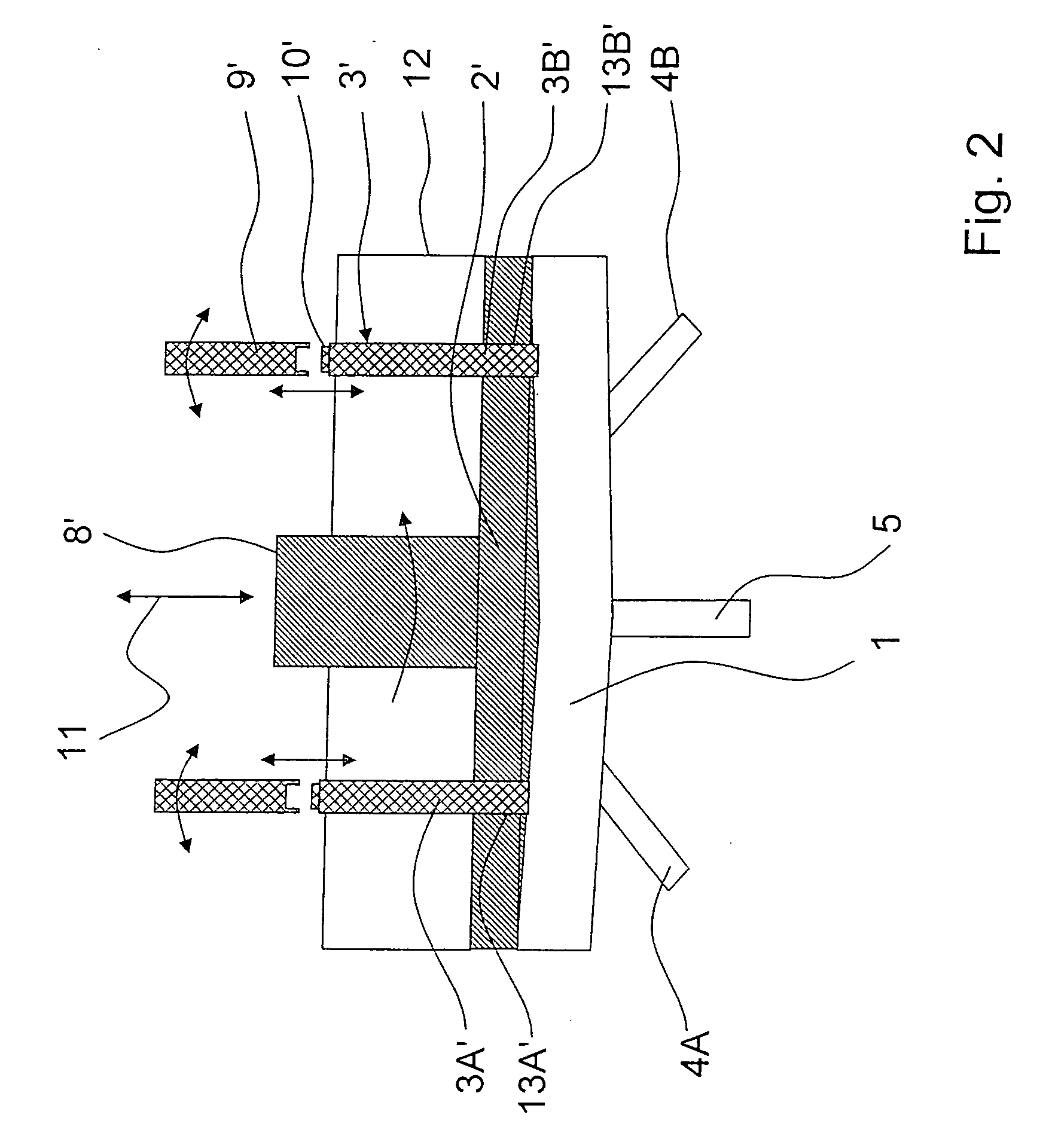
[0027] The exemplary embodiments shown in FIGS. 1 and 2 each show a device for mixing highly viscous fluids such as pastes, which is designed for integration into a system as well as for automated operation.

[0028] The device has one mixer housing 12, which essentially takes the form of a pot-like, cylindrical container.

[0029] Mixer housing 12 contains a mixing chamber 1, the volume of which is established by the inner wall of mixer housing 12 and a plunger 2 or 2′, which is designed piston-like having a piston rod 8 or 8′ and is moveable at least in a linear direction along an arrow 11 with respect to a bottom of mixer housing 12.

[0030] For charging mixing chamber 1 with the fluids to be mixed, two intake nipples 4A, 4B are formed at a bottom of mixer housing 12, the number of which may be varied in other variants according to the given requirements. Moreover, an outlet nipple 5 for removing the mixed media is located at the bottom of mixer housing 12.

[0031] In the variant accor...


PUM

PropertyMeasurementUnit
Viscosityaaaaaaaaaa
Volumeaaaaaaaaaa

Abstract

A device for mixing at least two media, in particular highly viscous media, having at least one mixing chamber, its volume in a mixer housing being variable by a movable plunger, and having at least one mixing tool. With the aid of an actuator, the mixing tool is insertable into the mixing chamber for mixing the media and is retractable from the mixing chamber following the mixing.

Description

FIELD OF THE INVENTION [0001] The present invention relates to a device for mixing at least two media, particularly highly viscous media. BACKGROUND INFORMATION [0002] A multitude of devices for mixing substances such as fluids, for example, which are used to mix components that differ in at least one property, are known to be in practical use. Depending on the given states of aggregation, the flow properties, the mixture ratios and the desired degree of homogenization of the media to be mixed, suitable devices are used for this purpose, having one or more chambers, in which the media to be mixed are located, and having mixing organs situated therein. [0003] For highly viscous media such as pastes, mixers are also known, in which a crosswise mixing of the media is achieved by artificially generated turbulences so as to achieve a sufficient intermixture. For highly viscous media, so-called spiral, anchor, coaxial and multi-shaft agitators are used as mixing organs. Furthermore, plane...

Claims


Application Information

Patent Timeline
IPC IPC(8): B01F7/00B01F29/86B01F29/60
CPCB01F3/10B01F7/00058B01F7/00116B01F7/0015B01F7/00258B01F2009/0092B01F9/106B01F15/0201B01F15/0237B01F15/0279B01F7/18B01F23/47B01F27/0541B01F27/0721B01F27/0725B01F27/1121B01F29/40221B01F29/82B01F27/90B01F35/7174B01F35/754251B01F35/718B01F35/75425
Inventor BRINZ, THOMASJOCKEL, JORGMULLER, ANDREAS
Owner ROBERT BOSCH GMBH
Learn More